Writeup LKSN ITNSA NTB 2021 - Network Actual & Future Network
Table Of Contents
Introduction
This write-up is based on the first of three questions titled “Actual Networks & Future Networks” from the NTB LKSN competition by ITNSA in 2021.
I discovered these questions while searching for lab exercises for CCNA. They consist of 20 questions that require configuring a Server, Router, Wireless Router, and Client Verification.
The skills required to solve these problems include:
- IP Addressing Configuration.
- Dynamic Host Configuration Protocol (DHCP) Server Configuration.
- Routing Protocol and Route Redistribution Configuration.
- VLAN Trunking Protocol (VTP) Configuration.
- Virtual Local Area Network (VLAN) Configuration.
- Wireless LAN Controller Configuration.
- Network Time Protocol (NTP) Configuration.
- Radius Configuration.
- Secure Shell (SSH) Configuration.
- Access Control List Configuration.
- IP Security (IPSec) Configuration.
- Role-Based Access Control Configuration.
- Network Address Translation (NAT) Configuration.
- Wide Area Network (WAN) Configuration.
This question is in .PKA format, which can be opened using Cisco Packet Tracer version 8.1.
For those interested, the questions can be downloaded from ITNSA.
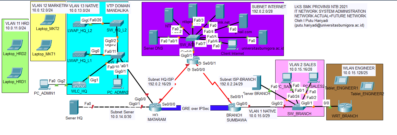
Task 1: HQ MATARAM Server Configuration
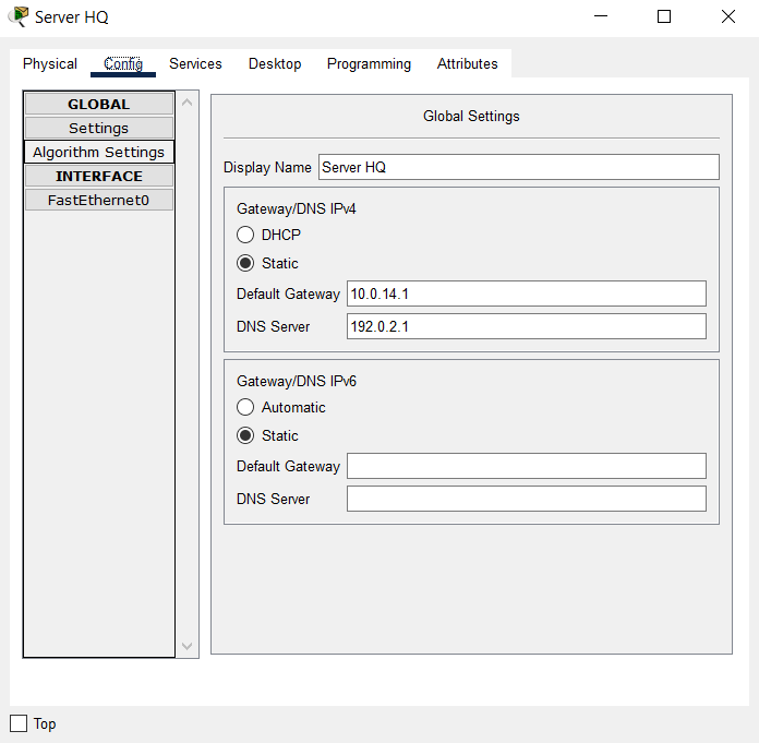
- Set the IP addressing and default gateway and DNS on the HQ Server with the following conditions:
- IP Address: the second IP address of subnet 10.0.14.0/30.
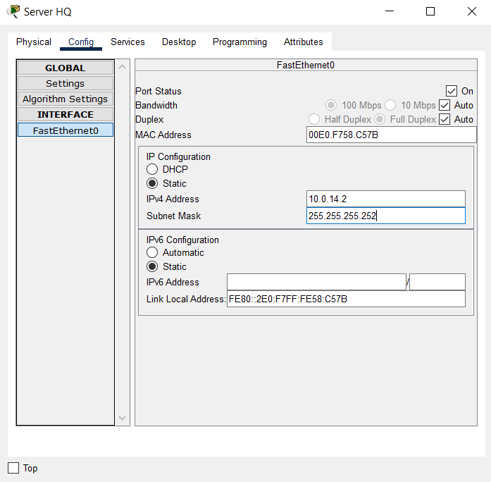
- Default Gateway: the first IP address of subnet 10.0.14.0/30.
- DNS Server: 192.0.2.1
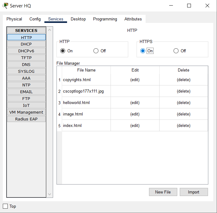
- Enable HTTP and HTTPS services.
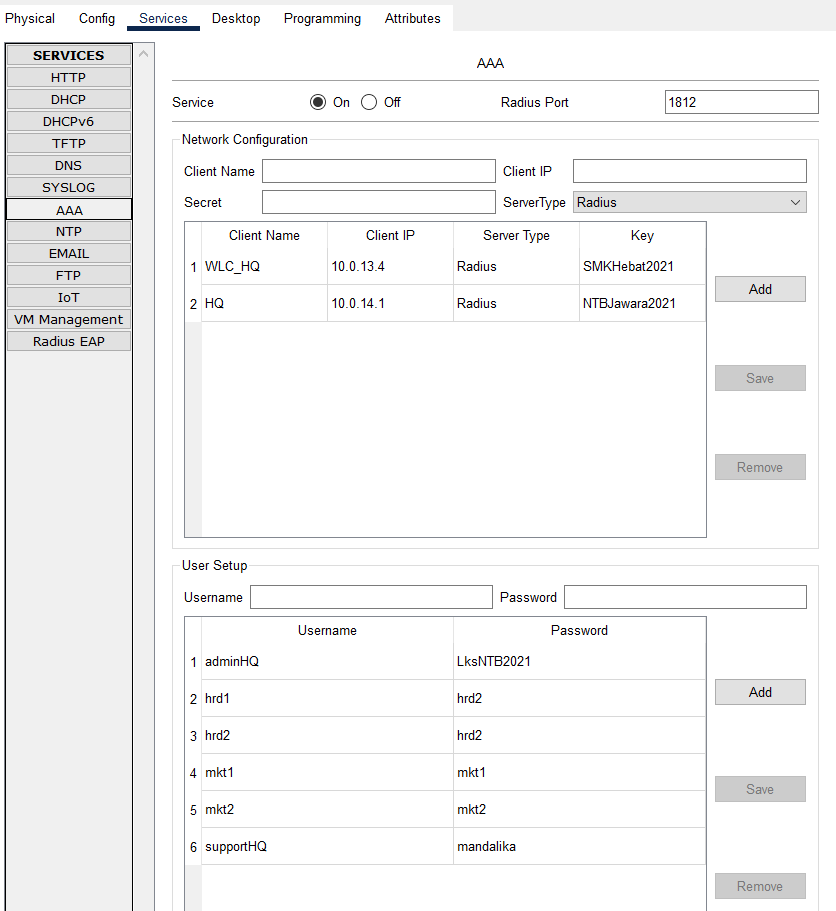
- Enable AAA service and configure Network Configuration with Server Radius type and User Setup as given in the table below:
| Client Name | Client IP | Key |
|---|---|---|
| WLC_HQ | 10.0.13.4 | SMKHebat2021 |
| HQ | 10.0.14.1 | NTBJawara2021 |
| Username | Password |
|---|---|
| hrd1 | hrd1 |
| hrd2 | hrd2 |
| mkt1 | mkt1 |
| mkt2 | mkt2 |
| adminHQ | LksNTB2021 |
| supportHQ | mandalika |
Completed Points: 8%
Task 2: HQ MATARAM Router Configuration
- Set the router’s hostname with the name “HQ”.
Router>en
Router#conf t
Enter configuration commands, one per line. End with CNTL/Z.
Router(config)#hostname HQ
- Set the encapsulation protocol on the Serial0/0/0 interface connected to the ISP router through PPP and use PPP authentication using CHAP with the password “LksNTB”.
HQ(config)#int s0/0/0
HQ(config-if)#encapsulation ppp
HQ(config-if)#ppp authentication chap
HQ(config)#username ISP password LksNTB
- Configure the IP addressing on the Serial0/0/0 interface connected to the ISP router with the second IP address from subnet 192.0.2.16/29.
HQ(config)#int s0/0/0
HQ(config-if)#ip address 192.0.2.18 255.255.255.248
HQ(config-if)#no shut
%LINK-5-CHANGED: Interface Serial0/0/0, changed state to up
%LINEPROTO-5-UPDOWN: Line protocol on Interface Serial0/0/0, changed state to up
HQ(config-if)#description TO ISP
- Configure the IP addressing on the GigabitEthernet0/1 interface connected to the HQ Server with the first IP address from subnet 10.0.14.0/30.
HQ(config)#int g0/1
HQ(config-if)#ip address 10.0.14.1 255.255.255.252
HQ(config-if)#no shut
%LINK-5-CHANGED: Interface GigabitEthernet0/1, changed state to up
%LINEPROTO-5-UPDOWN: Line protocol on Interface GigabitEthernet0/1, changed state to up
HQ(config-if)#description TO HQ Server
-
Create a subinterface on the GigabitEthernet0/0 interface that implements the IEEE 802.1Q encapsulation protocol and configure the router-on-stick for VLAN communication.
The following conditions are used to assign IP addresses to each subinterface:- Subinterface GigabitEthernet0/0.11 for VLAN 11 HRD with the first IP address of the subnet address 10.0.11.0/24.
- Subinterface GigabitEthernet0/0.12 for VLAN 12 MARKETING with the first IP address of the subnet address 10.0.12.0/24.
- Subinterface GigabitEthernet0/0.13 for VLAN 13 NATIVE is configured as a native VLAN and utilizes the first IP address in the subnet address 10.0.13.0/24.
HQ(config)#int g0/0
HQ(config-if)#description ROUTER-ON-STICK
%LINK-5-CHANGED: Interface GigabitEthernet0/0, changed state to up
HQ(config-if)#no shut
%LINEPROTO-5-UPDOWN: Line protocol on Interface GigabitEthernet0/0, changed state to up

HQ(config-if)#int g0/0.11
%LINK-5-CHANGED: Interface GigabitEthernet0/0.11, changed state to up
%LINEPROTO-5-UPDOWN: Line protocol on Interface GigabitEthernet0/0.11, changed state to up
HQ(config-subif)#description VLAN 11 HRD
HQ(config-subif)#encapsulation dot1Q 11
HQ(config-subif)#ip address 10.0.11.1 255.255.255.0

HQ(config)#int g0/0.12
%LINK-5-CHANGED: Interface GigabitEthernet0/0.12, changed state to up
%LINEPROTO-5-UPDOWN: Line protocol on Interface GigabitEthernet0/0.12, changed state to up
HQ(config-subif)#description VLAN 12 MARKETING
HQ(config-subif)#encapsulation dot1Q 12
HQ(config-subif)#ip address 10.0.12.1 255.255.255.0

HQ(config)#int g0/0.13
%LINK-5-CHANGED: Interface GigabitEthernet0/0.13, changed state to up
%LINEPROTO-5-UPDOWN: Line protocol on Interface GigabitEthernet0/0.13, changed state to up
HQ(config-subif)#description VLAN 13 NATIVE
HQ(config-subif)#encapsulation dot1Q 13 native
HQ(config-subif)#ip address 10.0.13.1 255.255.255.0
-
Creating a DHCP Server:
- Pool name “HRD” for VLAN 11 with subnet 10.0.11.0/24.
- Pool name “MARKETING” for VLAN 12 with subnet 10.0.12.0/24.
- Pool name “NATIVE” for VLAN 13 with subnet 10.0.13.0/24.
The TCP/IP parameters configured on each pool are as follows:
- The DHCP Client obtains the default gateway by using the first IP address of each VLAN.
- DNS for the entire pool utilizes the DNS ROOT Server’s IP address, which is 192.0.2.1.
- The IP address distribution of the Wireless Controller WLC HQ is also carried out for the “NATIVE” pool, specifically using the fourth IP address of the 10.0.13.0/24 subnet, so that the LeighWeight Access Point (LWAP) can register automatically.
For each pool, specify the IP address that is not leased to the DHCP Client:
- The initial IP address of the VLAN 11 HRD and VLAN 12 MARKETING subnet addresses.
- The first through fourth IP addresses of VLAN 13 NATIVE’s subnet addresses.
HQ(config)#ip dhcp pool HRD
HQ(dhcp-config)#network 10.0.11.0 255.255.255.0
HQ(dhcp-config)#default-router 10.0.11.1
HQ(dhcp-config)#dns-server 192.0.2.1

HQ(config)#ip dhcp pool MARKETING
HQ(dhcp-config)#network 10.0.12.0 255.255.255.0
HQ(dhcp-config)#default-router 10.0.12.1
HQ(dhcp-config)#dns-server 192.0.2.1

HQ(config)#ip dhcp pool NATIVE
HQ(dhcp-config)#network 10.0.13.0 255.255.255.0
HQ(dhcp-config)#default-router 10.0.13.1
HQ(dhcp-config)#dns-server 192.0.2.1
HQ(dhcp-config)#option 43 ip 10.0.13.4

HQ(config)#ip dhcp excluded-address 10.0.11.1
HQ(config)#ip dhcp excluded-address 10.0.12.1
HQ(config)#ip dhcp excluded-address 10.0.13.1 10.0.13.4
- Set the default route to the ISP using the gateway of the first IP address in the subnet 192.0.2.16/29 used by the ISP router’s Serial0/0/0 interface.
HQ(config)#ip route 0.0.0.0 0.0.0.0 192.0.2.17
-
Create an Extended Named ACL with the name “ALLOW-INTERNET” and the following conditions:
- Allow any source to send queries to the DNS server with the Public IP address 192.0.2.1 to translate domain names to IP addresses and vice versa.
- Allow Internet access ONLY to the gmail.com email service with a Public IP address of 192.0.2.5 for all hosts in VLAN 11 HRD with a subnet address of 10.0.11.0/24.
Ensure that only emails from gmail.com can be sent and received by the hosts on that VLAN. - Allow Internet connectivity to all hosts on VLAN 12 MARKETING with subnet address 10.0.12.0/24 and VLAN 13 NATIVE with subnet address 10.0.13.0/24.
HQ(config)#ip access-list extended ALLOW-INTERNET
HQ(config-ext-nacl)#permit udp any host 192.0.2.1 eq 53 (Query DNS)
HQ(config-ext-nacl)#permit tcp 10.0.11.0 0.0.0.255 192.0.2.5 0.0.0.0 eq 25  (Email)
HQ(config-ext-nacl)#permit tcp 10.0.11.0 0.0.0.255 192.0.2.5 0.0.0.0 eq 110 (Email)
HQ(config-ext-nacl)#permit tcp 10.0.12.0 0.0.0.255 0.0.0.0 255.255.255.255  (Internet)
HQ(config-ext-nacl)#permit tcp 10.0.13.0 0.0.0.255 0.0.0.0 255.255.255.255  (Internet)
- Set NAT Overload or Port Address Translation (PAT) for Standard Named ACL “ALLOW-INTERNET”.
HQ(config)#int s0/0/0
HQ(config-if)#ip nat outside
HQ(config)#int ra g0/0.11 - g0/0.13
HQ(config-if-range)#ip nat inside
HQ(config)#ip nat inside source list ALLOW-INTERNET interface s0/0/0 overload
- Set static NAT so that ONLY HTTP and HTTPS services on the HQ server with Private IP address 10.0.14.2 are translated to Public IP address 192.0.2.19.
HQ(config)#ip nat inside source static 10.0.14.2 192.0.2.19
HQ(config)#int g0/1
HQ(config-if-range)#ip nat inside
- Set up the HQ router to synchronize time with the NTP Server at IP address 192.0.2.2 and use md5 authentication with key 46 and password “NTBHebat2021”.
HQ(config)#ntp server 192.0.2.2 key 46
HQ(config)#ntp authentication-key 46 md5 NTBHebat2021
HQ(config)#ntp trusted-key 46
- Set the privilege mode password with the secret “LksNTB2021”.
HQ(config)#enable secret LksNTB2021
- Set the DNS server of the HQ router with IP address 192.0.2.1.
HQ(config)#ip name-server 192.0.2.1
- Enable SSH version 2 on the HQ router with the domain name “mandalika.id” and create RSA keys with modulus 1024.
HQ(config)#ip domain-name mandalika.id
HQ(config)#ip ssh version 2
HQ(config)#crypto key generate rsa general-keys modulus 1024
% You already have RSA keys defined named HQ.mandalika.id
% They will be replaced.

% The key modulus size is 1024 bits
% Generating 1024 bit RSA keys, keys will be non-exportable...[OK]
HQ(config)#
*Jul 22 14:10:45.255: %SSH-5-ENABLED: SSH 2 has been enabled
- Create a local authentication account on the HQ router with username “admin” and password “LksNTB2021”.
This account is a backup when authentication to the Radius server has problems.
HQ(config)#username admin privilege 15 secret LksNTB2021
HQ(config)#line vty 0 4
HQ(config-line)#login local
HQ(config-line)#transport input ssh
HQ(config)#line console 0
HQ(config-line)#login local
HQ(config)#line aux 0
HQ(config-line)#login local
- Enabled the AAA feature on the HQ router and set the default authentication to use the “local” database.
HQ(config)#aaa new-model
HQ(config)#aaa authentication login default local
- Creating a user login authentication list with the name “SERVER-AAA” that uses the Radius authentication method first, followed by “local”.
HQ(config)#aaa authentication login SERVER-AAA group RADIUS local
- Connect to the Radius Server with the second IP address of the subnet 10.0.14.0/30 and use the secret “NTBJawara2021”.
HQ(config)#radius server SERVER-AAA
HQ(config-RADIUS-server)#address ipv4 10.0.14.2 auth-port 1645
HQ(config-RADIUS-server)#key NTBJawara2021
- Set the HQ router to only accept remote access via SSH with a maximum number of sessions for 5 (five) users simultaneously and using the authentication list “SERVER-AAA”.
HQ(config)#line vty 0 4
HQ(config-line)#login authentication SERVER-AAA
HQ(config-line)#session-limit 5
- Set the console access to the router also to use the authentication list “SERVER-AAA” AUTHENTICATION LIST.
HQ(config)#line con 0
HQ(config-line)#login authentication SERVER-AAA
- Verify the configuration that has been done to ensure that it is following the requirements.
HQ#sh run
Building configuration...

Current configuration : 2932 bytes
!
version 15.1
no service timestamps log datetime msec
no service timestamps debug datetime msec
no service password-encryption
!
hostname HQ
!
enable secret 5 $1$mERr$ix/GaeUGI2eMcE7/bu9c2/
!
ip dhcp excluded-address 10.0.11.1
ip dhcp excluded-address 10.0.12.1
ip dhcp excluded-address 10.0.13.1 10.0.13.4
!
ip dhcp pool HRD
network 10.0.11.0 255.255.255.0
default-router 10.0.11.1
dns-server 192.0.2.1
ip dhcp pool MARKETING
network 10.0.12.0 255.255.255.0
default-router 10.0.12.1
dns-server 192.0.2.1
ip dhcp pool NATIVE
network 10.0.13.0 255.255.255.0
default-router 10.0.13.1
dns-server 192.0.2.1
!
aaa new-model
!
aaa authentication login SERVER-AAA group RADIUS local
aaa authentication login default local
!
no ip cef
no ipv6 cef
!
username ISP password 0 LksNTB
username admin privilege 15 secret 5 $1$mERr$ix/GaeUGI2eMcE7/bu9c2/
!
license udi pid CISCO1941/K9 sn FTX1524O1D2-
license boot module c1900 technology-package securityk9
!
ip ssh version 2
ip domain-name mandalika.id
ip name-server 192.0.2.1
!
spanning-tree mode pvst
!
interface GigabitEthernet0/0
description ROUTER-ON-STICK
no ip address
duplex auto
speed auto
!
interface GigabitEthernet0/0.11
description VLAN 11 HRD
encapsulation dot1Q 11
ip address 10.0.11.1 255.255.255.0
ip nat inside
!
interface GigabitEthernet0/0.12
description VLAN 12 MARKETING
encapsulation dot1Q 12
ip address 10.0.12.1 255.255.255.0
ip nat inside
!
interface GigabitEthernet0/0.13
description VLAN 13 NATIVE
encapsulation dot1Q 13 native
ip address 10.0.13.1 255.255.255.0
ip nat inside
!
interface GigabitEthernet0/1
description TO HQ SERVER
ip address 10.0.14.1 255.255.255.252
ip nat inside
duplex auto
speed auto
!
interface Serial0/0/0
description TO ISP
ip address 192.0.2.18 255.255.255.248
encapsulation ppp
ppp authentication chap
ip nat outside
!
interface Serial0/0/1
no ip address
clock rate 2000000
shutdown
!
interface Vlan1
no ip address
shutdown
!
ip nat inside source list ALLOW-INTERNET interface Serial0/0/0 overload
ip nat inside source static 10.0.14.2 192.0.2.19
ip classless
ip route 0.0.0.0 0.0.0.0 192.0.2.17
!
ip flow-export version 9
!
ip access-list extended ALLOW-INTERNET
permit udp any host 192.0.2.1 eq domain
permit tcp 10.0.11.0 0.0.0.255 host 192.0.2.5 eq smtp
permit tcp 10.0.11.0 0.0.0.255 host 192.0.2.5 eq pop3
permit tcp 10.0.12.0 0.0.0.255 any
permit tcp 10.0.13.0 0.0.0.255 any
!
no cdp run
!
radius server SERVER-AAA
address ipv4 10.0.14.2 auth-port 1645
key NTBJawara2021
radius server 10.0.14.2
address ipv4 10.0.14.2 auth-port 1645
key NTBJawara2021
!
line con 0
login authentication SERVER-AAA
!
line aux 0
!
line vty 0 4
session-limit 5
login authentication SERVER-AAA
transport input ssh
!
ntp authentication-key 46 md5 080F786C211C071606595C567B 7
ntp trusted-key 46
ntp server 192.0.2.2 key 46
!
end

HQ#
Completed Points: 19%
Task 3: SW_HQ_L1 Switch Configuration at HQ MATARAM
- Set the hostname of the Switch with the name “SW_HQ_L1”.
Switch>en
Switch#conf t
Enter configuration commands, one per line.  End with CNTL/Z.
Switch(config)#hostname SW_HQ_L1
- Set the VTP with the domain name “MANDALIKA” and password using “LksNTB”.
SW_HQ_L1(config)#vtp domain MANDALIKA
Changing VTP domain name from NULL to MANDALIKA
SW_HQ_L1(config)#vtp password LksNTB
Setting device VLAN database password to LksNTB
- Creating new VLANs, among others:
- VLAN 11 with the name HRD.
- VLAN 12 with the name MARKETING.
- VLAN 13 with the name NATIVE.
SW_HQ_L1(config)#vlan 11
SW_HQ_L1(config-vlan)#name HRD
SW_HQ_L1(config-vlan)#vlan 12
SW_HQ_L1(config-vlan)#name MARKETING
SW_HQ_L1(config-vlan)#vlan 13
SW_HQ_L1(config-vlan)#name NATIVE
SW_HQ_L1#sh vlan
VLAN Name                             Status    Ports
---- -------------------------------- --------- -------------------------------
11   HRD                              active
12   MARKETING                        active
13   NATIVE                           active
- Set the IP addressing on the VLAN 13 interface with the second IP address of the subnet address 10.0.13.0/24.
SW_HQ_L1(config)#int vlan 13
%LINK-5-CHANGED: Interface Vlan13, changed state to up
SW_HQ_L1(config-if)#ip address 10.0.13.2 255.255.255.0
- Set the default gateway using the first IP address of the subnet address 10.0.13.0/24, one of the IP addresses on the HQ router, so that it can communicate with different networks.
SW_HQ_L1(config)#ip default-gateway 10.0.13.1
- Assign port FastEthernet0/1 to be a member of VLAN 13.
SW_HQ_L1(config)#int fa0/1
SW_HQ_L1(config-if)#switchport mode access
SW_HQ_L1(config-if)#switchport access vlan 13
%LINEPROTO-5-UPDOWN: Line protocol on Interface Vlan13, changed state to up
- Enable port mode to trunk for interfaces FastEthernet0/10, FastEthernet0/11, GigabitEthernet0/1 and GigabitEthernet0/2. Notes: VLAN 13 is enabled as a native VLAN.
SW_HQ_L1(config)#int ra fa0/10 - fa0/11
SW_HQ_L1(config-if-range)#switchport mode trunk
SW_HQ_L1(config-if-range)#switchport trunk native vlan 13
SW_HQ_L1(config-if-range)#switchport trunk allowed vlan 11,12,13

%LINEPROTO-5-UPDOWN: Line protocol on Interface FastEthernet0/10, changed state to down
%LINEPROTO-5-UPDOWN: Line protocol on Interface FastEthernet0/10, changed state to up
%LINEPROTO-5-UPDOWN: Line protocol on Interface FastEthernet0/11, changed state to down
%LINEPROTO-5-UPDOWN: Line protocol on Interface FastEthernet0/11, changed state to up

SW_HQ_L1(config)#int ra g0/1 - g0/2
SW_HQ_L1(config-if-range)#switchport mode trunk
SW_HQ_L1(config-if-range)#switchport trunk native vlan 13
SW_HQ_L1(config-if-range)#switchport trunk allowed vlan 11,12,13

%LINEPROTO-5-UPDOWN: Line protocol on Interface GigabitEthernet0/1, changed state to down
%LINEPROTO-5-UPDOWN: Line protocol on Interface GigabitEthernet0/1, changed state to up
%LINEPROTO-5-UPDOWN: Line protocol on Interface GigabitEthernet0/2, changed state to down
%LINEPROTO-5-UPDOWN: Line protocol on Interface GigabitEthernet0/2, changed state to up
- Verify the configuration that has been done to ensure that it is following the requirements.
SW_HQ_L1#sh run
Building configuration...

Current configuration : 1591 bytes
!
version 15.0
no service timestamps log datetime msec
no service timestamps debug datetime msec
no service password-encryption
!
hostname SW_HQ_L1
!
spanning-tree mode pvst
spanning-tree extend system-id
!
interface FastEthernet0/1
switchport access vlan 13
switchport mode access
!
interface FastEthernet0/10
switchport trunk native vlan 13
switchport trunk allowed vlan 11-13
switchport mode trunk
!
interface FastEthernet0/11
switchport trunk native vlan 13
switchport trunk allowed vlan 11-13
switchport mode trunk
!
interface GigabitEthernet0/1
switchport trunk native vlan 13
switchport trunk allowed vlan 11-13
switchport mode trunk
!
interface GigabitEthernet0/2
switchport trunk native vlan 13
switchport trunk allowed vlan 11-13
switchport mode trunk
!
interface Vlan1
no ip address
shutdown
!
interface Vlan13
ip address 10.0.13.2 255.255.255.0
!
ip default-gateway 10.0.13.1
!
line con 0
!
line vty 0 4
login
line vty 5 15
login
!
end

SW_HQ_L1#
Completed Points: 5%
Task 4: SW_HQ_L2 Switch Configuration at HQ MATARAM
- Set the hostname of the Switch with the name “SW_HQ_L2”.
Switch#en
Switch#conf t
Enter configuration commands, one per line.  End with CNTL/Z.
Switch(config)#hostname SW_HQ_L2
- Set up VTP with Client mode, domain name “MANDALIKA” and password using “LksNTB”.
SW_HQ_L2(config)#vtp mode client
Setting device to VTP CLIENT mode.
SW_HQ_L2(config)#vtp domain MANDALIKA
Changing VTP domain name from NULL to MANDALIKA
SW_HQ_L2(config)#vtp password LksNTB
Setting device VLAN database password to LksNTB
- Set the IP addressing on interface VLAN 13 with the third IP address from subnet address 10.0.13.0/24.
SW_HQ_L2(config)#int vlan 13
SW_HQ_L2(config-if)#ip address 10.0.13.3 255.255.255.0
- Set the default gateway using the first IP address of the subnet address 10.0.13.0/24, one of the IP addresses on the HQ router, so that it can communicate with different networks.
SW_HQ_L2(config)#ip default-gateway 10.0.13.1
- Enable port mode to trunk for the FastEthernet0/20 and GigabitEthernet0/2 interfaces.
Notes: VLAN 13 is enabled as a native VLAN.
SW_HQ_L2(config)#int fa0/20
SW_HQ_L2(config-if)#switchport mode trunk
SW_HQ_L2(config-if-range)#switchport trunk native vlan 13
SW_HQ_L2(config-if-range)#switchport trunk allowed vlan 11,12,13
%LINEPROTO-5-UPDOWN: Line protocol on Interface FastEthernet0/20, changed state to down
%LINEPROTO-5-UPDOWN: Line protocol on Interface FastEthernet0/20, changed state to up

SW_HQ_L2(config-if)#int g0/2
SW_HQ_L2(config-if)#switchport mode trunk
SW_HQ_L2(config-if-range)#switchport trunk native vlan 13
SW_HQ_L2(config-if-range)#switchport trunk allowed vlan 11,12,13
%LINEPROTO-5-UPDOWN: Line protocol on Interface GigabitEthernet0/2, changed state to down
%LINEPROTO-5-UPDOWN: Line protocol on Interface GigabitEthernet0/2, changed state to up
- Verify the configuration that has been done to ensure that it is following the requirements
SW_HQ_L2#sh run
Building configuration...

Current configuration : 1354 bytes
!
version 15.0
no service timestamps log datetime msec
no service timestamps debug datetime msec
no service password-encryption
!
hostname SW_HQ_L2
!
spanning-tree mode pvst
spanning-tree extend system-id
!
interface FastEthernet0/20
switchport trunk native vlan 13
switchport trunk allowed vlan 11-13
switchport mode trunk
!
interface GigabitEthernet0/2
switchport trunk native vlan 13
switchport trunk allowed vlan 11-13
switchport mode trunk
!
interface Vlan1
no ip address
shutdown
!
interface Vlan13
ip address 10.0.13.3 255.255.255.0
!
ip default-gateway 10.0.13.1
!
line con 0
!
line vty 0 4
login
line vty 5 15
login
!
end

SW_HQ_L2#
Completed Points: 3%
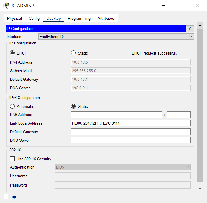
Task 5: Admin2 PC Configuration and Verification at HQ MATARAM
- Set up the DHCP Client on the Admin2 PC at the MATARAM head office.
Ensure the PC successfully obtains dynamic IP addressing from the DHCP Server.
- Verify PC Admin2 to Switch SW_HQ_L1 and Router HQ using Simple PDU.
Make sure the connection is successful.

Completed Points: 0%
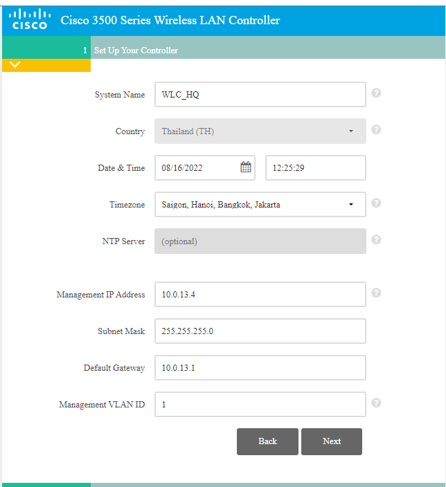
Task 6: WLC Configuration at HQ MATARAM
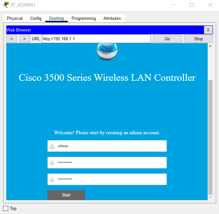
- Perform the initial setup on the WLC HQ using the browser from the PC Admin1 desktop by entering the WLC’s IP address, which is http://192.168.1.1.
Create a new administrator account with the username “admin” and the password “LksNTB2021.”
-
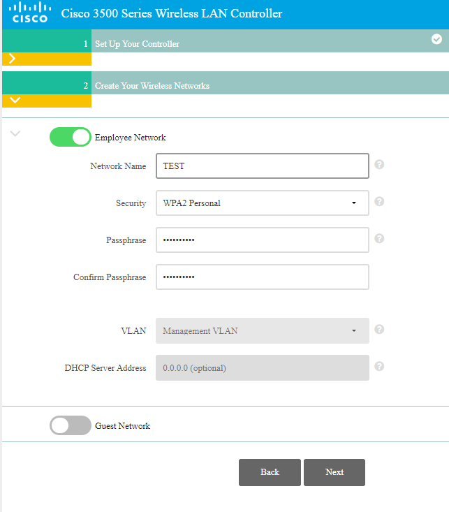
Configure the Controller with the following conditions:
- System Name: WLC_HQ
- Management IP Address: using the 4th IP address from subnet 10.0.13.0/24
- Default Gateway: using the 1st IP address from subnet 10.0.13.0/24
- Management VLAN ID: 1
- WLAN configuration with Network Name “TEST” and Passphrase “LksNTB2021”.
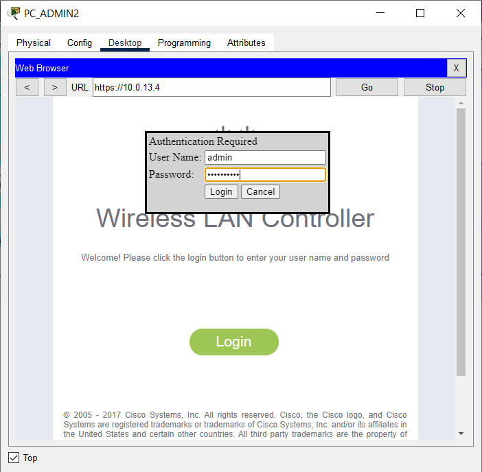
- After the initial setup is completed, the WLC_HQ configuration can be done through a browser from the PC_Admin2 desktop by accessing the IP address of the WLC via HTTPS, https://10.0.13.4.
Login using username “admin” and password “LksNTB2021”.
- Delete the WLAN with Network Name “TEST”.

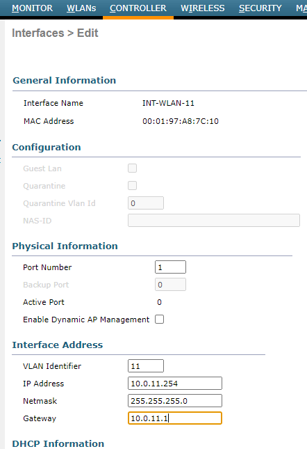
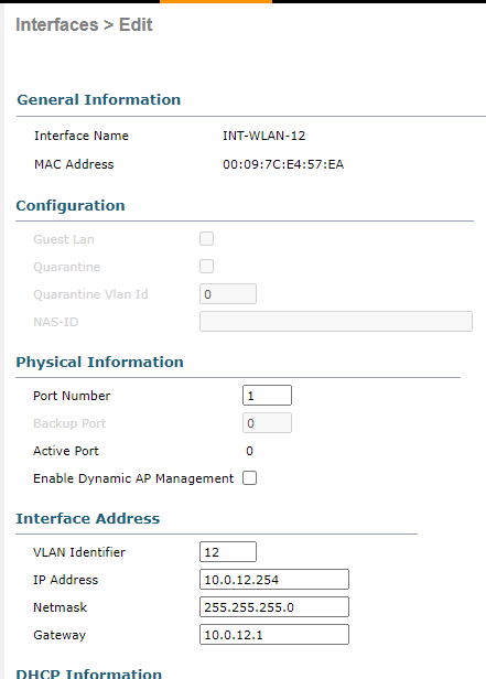
- Configure a new VLAN interface on the WLC with the following requirements:
| Interface | VLAN | Port | IP Address | Gateway |
|---|---|---|---|---|
| INT-WLAN-11 | 11 | 1 | 10.0.11.254/24 | 10.0.11.1 |
| INT-WLAN-12 | 12 | 1 | 10.0.12.254/24 | 10.0.12.1 |
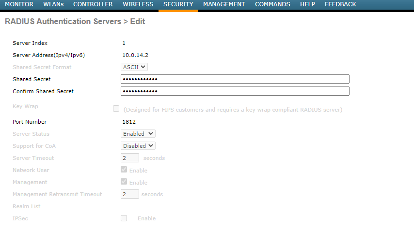
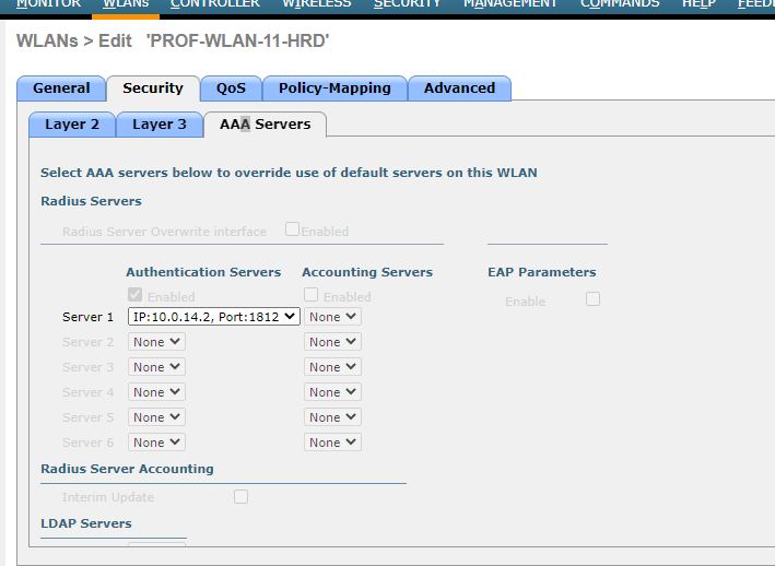
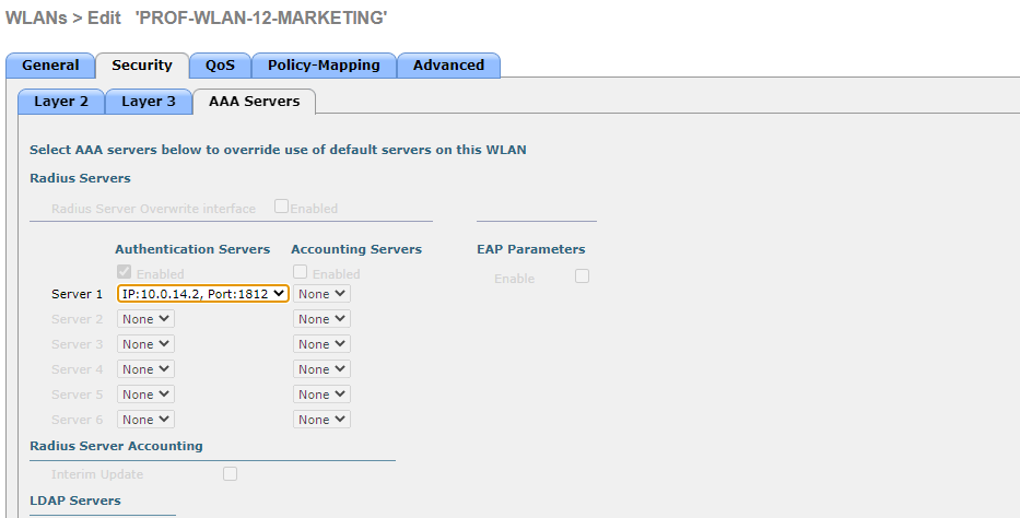
- Configure the WLC to authenticate WLAN users using a RADIUS server with the subnet’s second IP address, 10.0.14.0/30, and the shared secret “SMKHebat2021”.
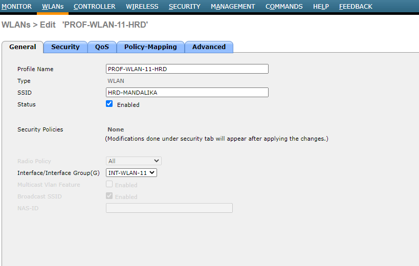
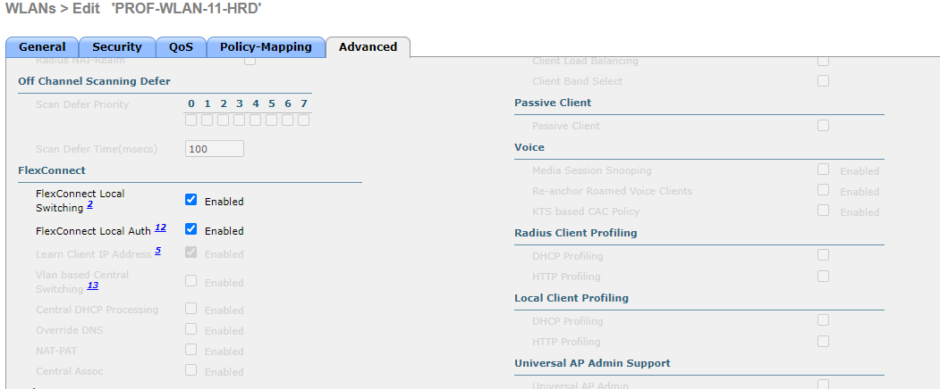
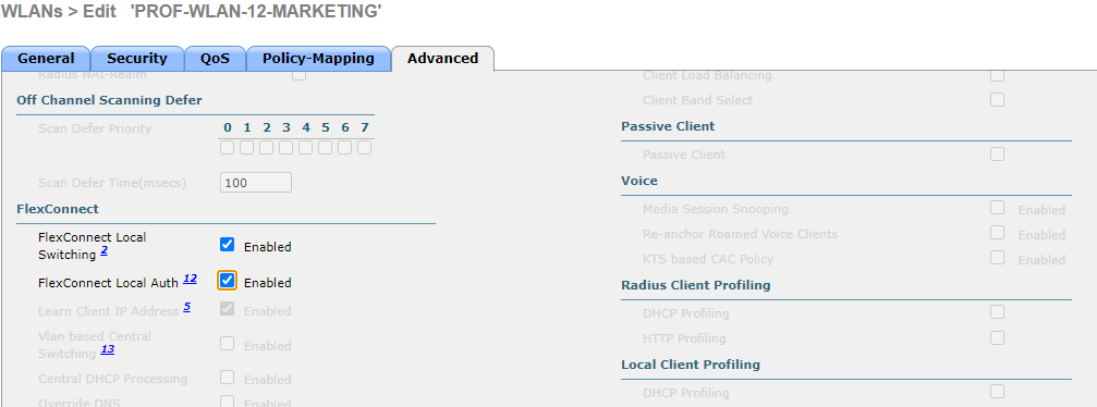
- Configure a new WLAN on the WLC with the following requirements:
| Profile Name | SSID | ID | Interface | FlexConnect |
|---|---|---|---|---|
| PROF-WLAN-11-HRD | HRD-MANDALIKA | 1 | INT-WLAN-11 | Local Switching & Local Auth |
| PROF-WLAN-12-MARKETING | MARKETING-MANDALIKA | 2 | INT-WLAN-12 | Local Switching & Local Auth |
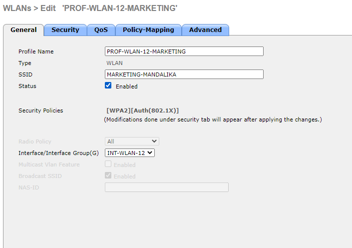
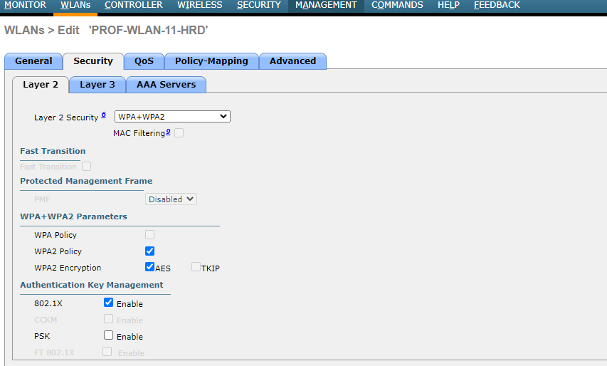
- Use WPA2-Enterprise to secure each WLAN.
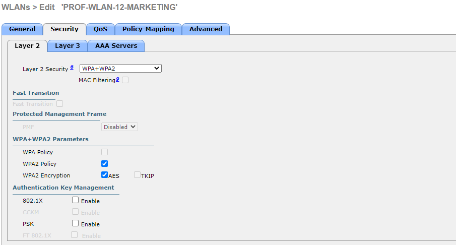
Completed Points: 8%
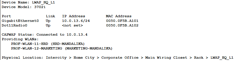
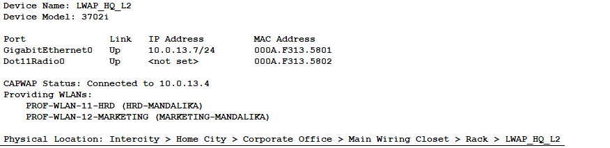
Task 7: LWAP Configuration at HQ MATARAM
- Configure IP addressing dynamically or as a DHCP Client on LWAP_HQ_L1 and LWAP_HQ_L2.
Double-check the setup to ensure that each LWAP has received dynamic IP addresses from the DHCP Server.
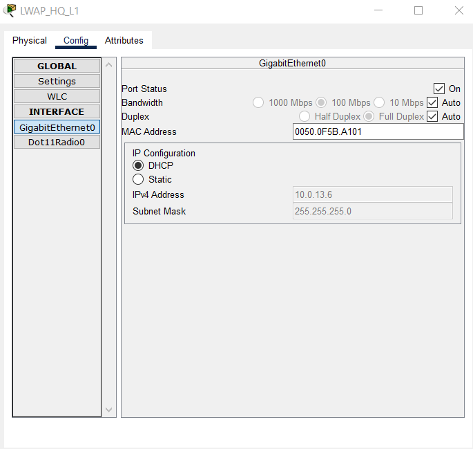
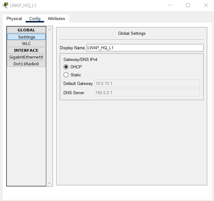
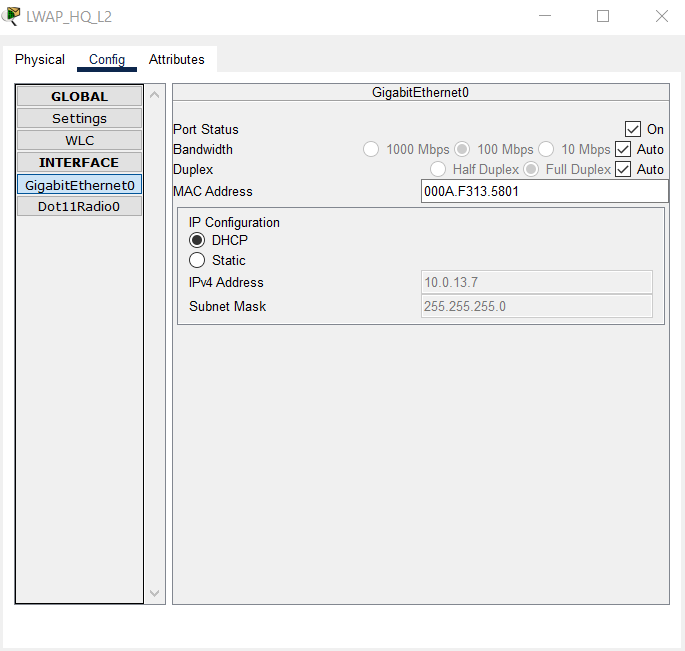
- Also, check that the CWAP Status of each LWAP indicates that it has successfully connected to the IP address of the WLC HQ and provides two WLANs, HRD-MANDALIKA and MARKETING-MANDALIKA.
Completed Points: 0%
Task 8: End Device Configuration and Verification on HRD and MARKETING VLANs at HQ MATARAM
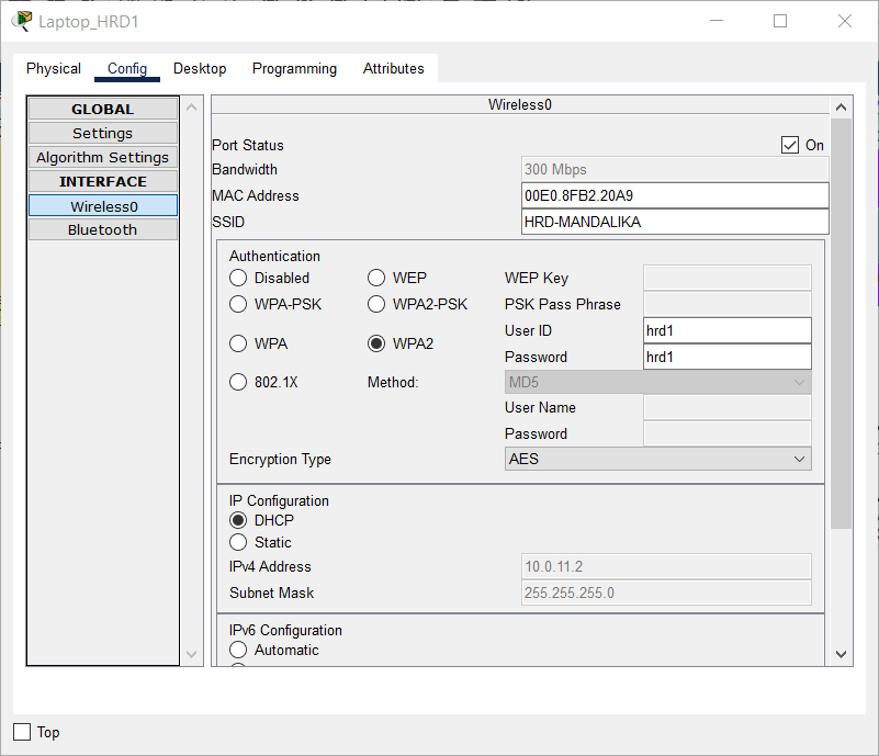
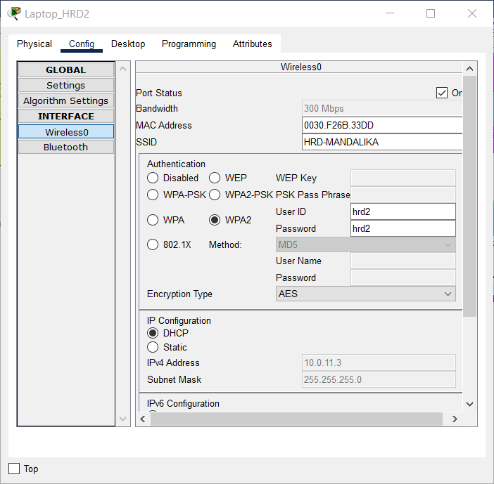
-
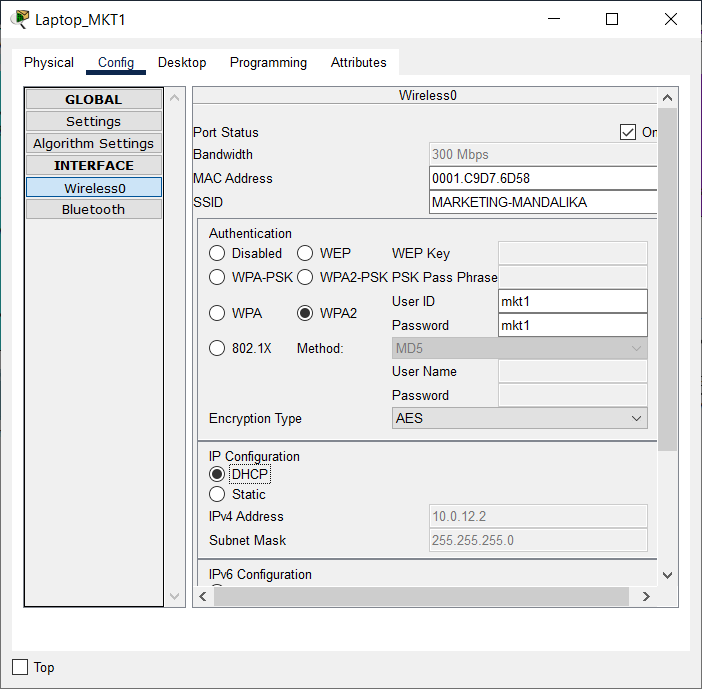
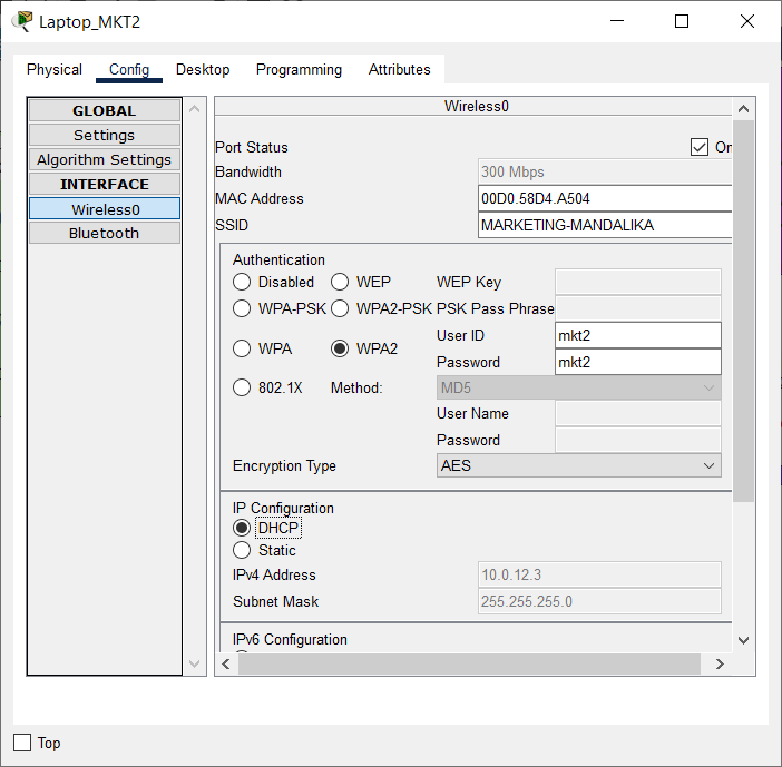
Set the DHCP Client on the Wireless0 interface of each End Device on VLAN HRD and MARKETING, namely Laptop_HRD1, Laptop_HRD2, Laptop_MKT1, and Laptop_MKT2, to get dynamic IP addressing from the DHCP Server.
Use an authentication account as mentioned in the table below:
Connect Laptop_HRD1 and Laptop_HRD2 in VLAN HRD to LWAP with SSID “HRD-MANDALIKA” and Wireless Security Configuration WPA2-Enterprise.
| Login Name | Password | Device Name |
|---|---|---|
| hrd1 | hrd1 | Laptop_HRD1 |
| hrd2 | hrd2 | Laptop_HRD2 |
Connect Laptop_MKT1 and Laptop_MKT2 in VLAN MARKETING to LWAP with SSID “MARKETING-MANDALIKA” with Wireless Security Configuration WPA2-Enterprise.
Use an authentication account, as shown in the following table:
| Login Name | Password | Device Name |
|---|---|---|
| mkt1 | mkt1 | Laptop_MKT1 |
| mkt2 | mkt2 | Laptop_MKT2 |
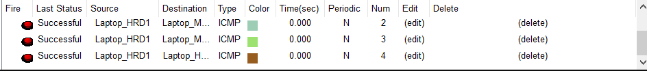
- Using a simple PDU, check the connections between each laptop and the other laptop in the HQ MATARAM.
Check that the connection is working properly.
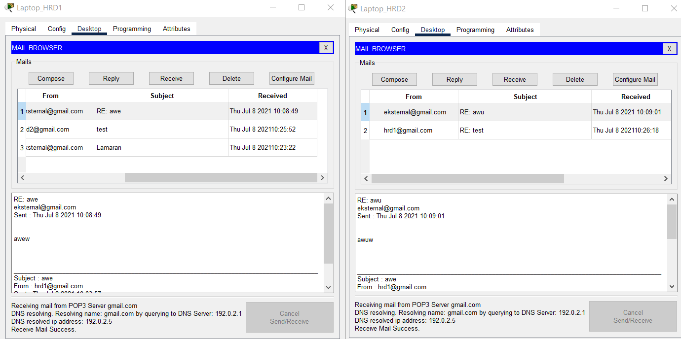
- Check the Internet connection of Laptop_HRD1 and Laptop_HRD2 in VLAN MARKETING by sending an email to external@gmail.com.
The title and email message used for testing can be chosen independently.
Check that the email is properly sent from Laptop HRD1 and Laptop HRD2.
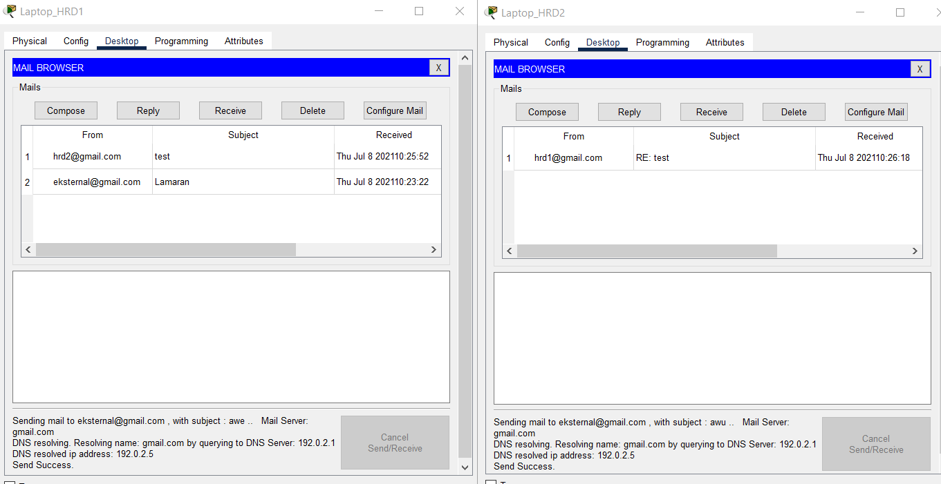
- Verify that the emails sent from Laptop_HRD1 and Laptop_HRD2 were successfully received via PC Client Internet on the Internet subnet.
Respond to each of these emails.
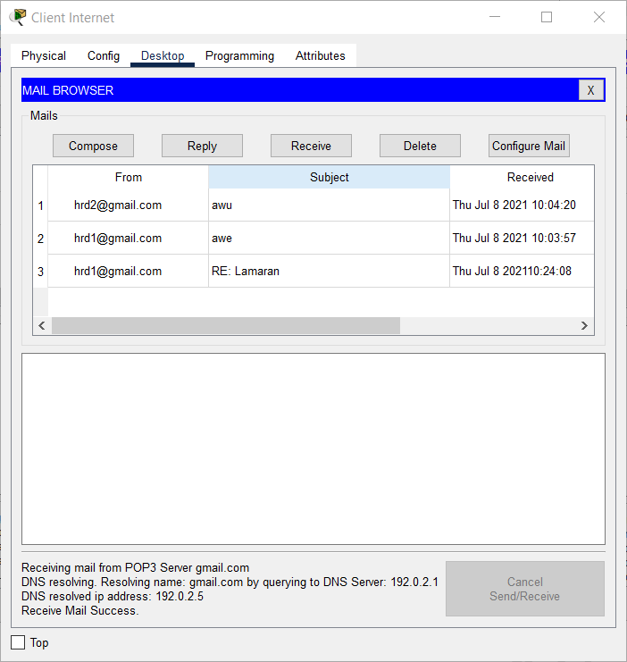
- Verify that the email has been downloaded successfully from Laptop_HRD1 and Laptop_HRD2.
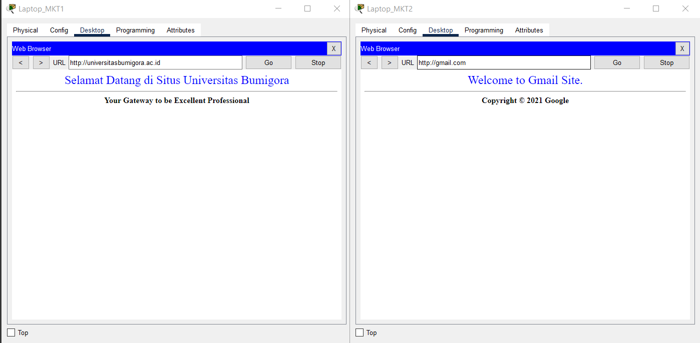
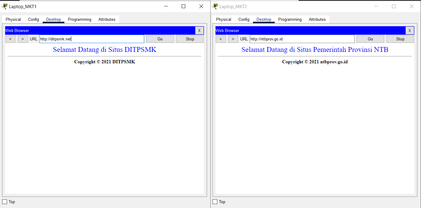
- Verify the Internet connection of Laptop_MKT1 and Laptop_MKT2 in VLAN MARKETING using a browser by visiting ntbprov.go.id, ditpsmk.net, gmail.com, and universitasbumigora.ac.id.
Check that the connection is working properly.
Completed Points: 0%
Task 9: BRANCH SUMBAWA Server Configuration
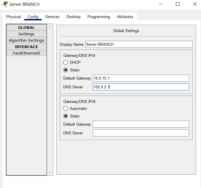
- Set the IP addressing and default gateway and DNS on the BRANCH Server with the following conditions:
- IP Address: the fourth IP address of subnet 10.0.15.0/29.
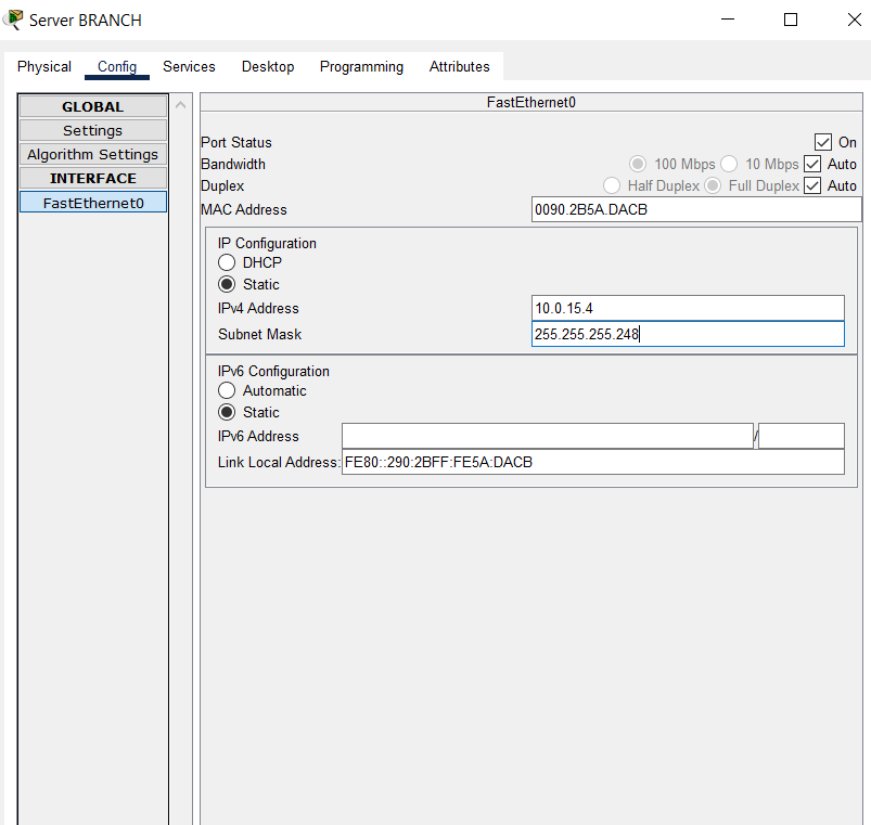
- Default Gateway: the first IP address of subnet 10.0.15.0/29.
- DNS Server: 192.0.2.1
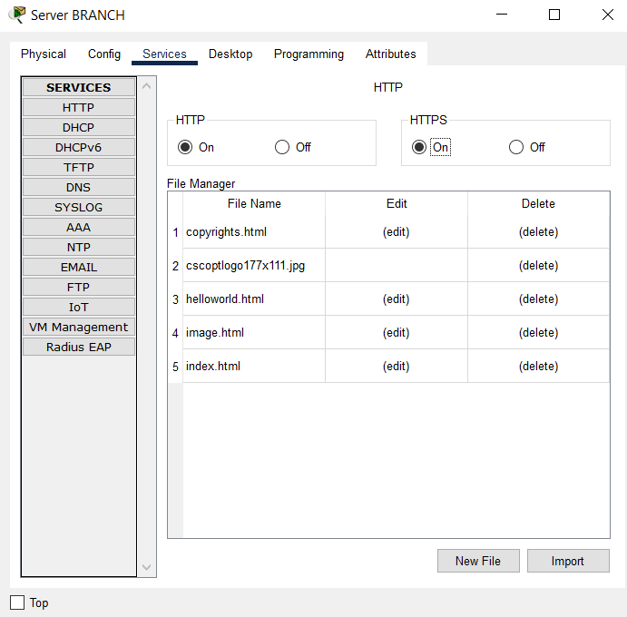
- Enable HTTP and HTTPS services.
- Enable AAA service and configure Network Configuration with Server Radius type and User Setup as given in the table below:
| Client Name | Client IP | Key |
|---|---|---|
| BRANCH | 10.0.13.4 | SMKHebat2021 |
| SW_BRANCH | 10.0.14.1 | NTBJawara2021 |
| WRT_BRANCH | 10.10.15.3 | SMKBisa2021 |
| Username | Password |
|---|---|
| sales1 | hrd1 |
| sales2 | hrd2 |
| engineer1 | mkt1 |
| engineer2 | mkt2 |
| adminBRANCH | LksNTB2021 |
| helpdeskBRANCH | mandalika |
Completed Points: 10%
Task 10: BRANCH SUMBAWA Router Configuration
- Set the router’s hostname with the name “BRANCH”.
Router>en
Router#conf t
Enter configuration commands, one per line.  End with CNTL/Z.
Router(config)#hostname BRANCH
- Set the encapsulation protocol on the Serial0/0/1 interface connected to the ISP router through PPP and use PPP authentication using CHAP with the password “LksNTB”.
BRANCH(config)#int s0/0/1
BRANCH(config-if)#encapsulation ppp
BRANCH(config-if)#ppp authentication chap
BRANCH(config-if)#exit
BRANCH(config)#username ISP password LksNTB
- Configure the IP addressing on the Serial0/0/1 interface connected to the ISP router with the second IP address from subnet 192.0.2.24/29.
BRANCH(config)#int s0/0/1
BRANCH(config-if)#ip address 192.0.2.26 255.255.255.248
BRANCH(config-if)#no shut
%LINK-5-CHANGED: Interface Serial0/0/1, changed state to up
%LINEPROTO-5-UPDOWN: Line protocol on Interface Serial0/0/1, changed state to up
-
Create a subinterface on the GigabitEthernet0/0 interface that implements the IEEE 802.1Q encapsulation protocol and configure the router-on-stick for VLAN communication.
The following conditions are used to assign IP addresses to each subinterface:- Subinterface GigabitEthernet0/0.1 for VLAN 1 NATIVE with the first IP address of the subnet address 10.0.15.0/29.
- Subinterface GigabitEthernet0/0.2 for VLAN 2 SALES with the first IP address of the subnet address 10.0.15.16/28.
BRANCH(config)#int g0/0
BRANCH(config-if)#description ROUTER-ON-STICK
BRANCH(config-if)#no shut
%LINK-5-CHANGED: Interface GigabitEthernet0/0, changed state to up
%LINEPROTO-5-UPDOWN: Line protocol on Interface GigabitEthernet0/0, changed state to up

%LINK-5-CHANGED: Interface GigabitEthernet0/0.1, changed state to up
BRANCH(config)#int g0/0.1
%LINEPROTO-5-UPDOWN: Line protocol on Interface GigabitEthernet0/0.1, changed state to up
BRANCH(config-subif)#encapsulation dot1Q 1
BRANCH(config-subif)#ip address 10.0.15.1 255.255.255.248

BRANCH(config)#int g0/0.2
%LINK-5-CHANGED: Interface GigabitEthernet0/0.2, changed state to up
%LINEPROTO-5-UPDOWN: Line protocol on Interface GigabitEthernet0/0.2, changed state to up
BRANCH(config-subif)#encapsulation dot1Q 2
BRANCH(config-subif)#ip address 10.0.15.17 255.255.255.240
BRANCH(config-subif)#description SALES
BRANCH(config-subif)#exit
-
Creating a DHCP Server:
- Pool name “SALES” for VLAN 11 with subnet 10.0.15.16/28.
TCP/IP parameters are set:
- The pool includes the default gateway, which uses the subnet’s initial IP address, 10.0.15.16/28.
- DNS server at 192.0.2.1.
- Set the first IP address of subnet 10.0.15.16/28 to not be leased to DHCP Client.
BRANCH(config)#ip dhcp pool SALES
BRANCH(dhcp-config)#network 10.0.15.16 255.255.255.240
BRANCH(dhcp-config)#default-router 10.0.15.17
BRANCH(dhcp-config)#dns-server 192.0.2.1
BRANCH(config)#ip dhcp excluded-address 10.0.15.17
- Set the default route to the ISP using the gateway of the first IP address in the subnet 192.0.2.24/29 used by the ISP router’s Serial0/0/1 interface.
BRANCH(config)#ip route 0.0.0.0 0.0.0.0 192.0.2.25
- Create a Standard Named ACL called “ALLOW-INTERNET” that permits Internet access to all hosts on subnet addresses 10.0.15.0/29 and 10.0.15.16/28.
BRANCH(config)#ip access-list standard ALLOW-INTERNET
BRANCH(config-std-nacl)#permit 10.0.15.0 0.0.0.7
BRANCH(config-std-nacl)#permit 10.0.15.16 0.0.0.15
- Set NAT Overload or Port Address Translation (PAT) for Standard Named ACL “ALLOW-INTERNET”.
BRANCH(config)#int s0/0/1
BRANCH(config-if)#ip nat outside
BRANCH(config)#int ra g0/0.1 - g0/0.2
BRANCH(config-if-range)#ip nat inside
BRANCH(config)#ip nat inside source list ALLOW-INTERNET interface s0/0/1 overload
- Set static NAT so that ONLY HTTP and HTTPS services on the BRANCH server with Private IP address 10.0.15.4 are translated to Public IP address 192.0.2.27.
BRANCH(config)#ip nat inside source static 10.0.15.4 192.0.2.27
- Set up the BRANCH router to synchronize time with the NTP Server at IP address 192.0.2.2 and use md5 authentication with key 46 and password “NTBHebat2021”.
BRANCH(config)#ntp server 192.0.2.2 key 46
BRANCH(config)#ntp authentication-key 46 md5 NTBHebat2021
BRANCH(config)#ntp trusted-key 46
- Set the privilege mode password with the secret “LksNTB2021”.
BRANCH(config)#enable secret LksNTB2021
- Set the DNS server of the BRANCH router with IP address 192.0.2.1.
BRANCH(config)#ip name-server 192.0.2.1
- Enable SSH version 2 on the BRANCH router with the domain name “branch.mandalika.id” and create RSA keys with modulus 1024.
BRANCH(config)#ip domain-name branch.mandalika.id
BRANCH(config)#ip ssh version 2
BRANCH(config)#crypto key generate rsa general-keys modulus 1024
% You already have RSA keys defined named BRANCH.branch.mandalika.id
% They will be replaced.

% The key modulus size is 1024 bits
% Generating 1024 bit RSA keys, keys will be non-exportable...[OK]
%SSH-5-ENABLED: SSH 2 has been enabled
- Create a local authentication account on the BRANCH router with username “admin” and password “LksNTB2021”. This account is a backup when authentication to the Radius server has problems.
BRANCH(config)#username admin privilege 15 secret LksNTB2021
BRANCH(config)#line vty 0 4
BRANCH(config-line)#login local
BRANCH(config-line)#transport input ssh
BRANCH(config)#line console 0
BRANCH(config-line)#login local
BRANCH(config)#line aux 0
BRANCH(config-line)#login local
- Enabled the AAA feature on the BRANCH router and set the default authentication to use the “local” database.
BRANCH(config)#aaa new-model
BRANCH(config)#aaa authentication login default local
- Creating a user login authentication list with the name “SERVER-AAA” that uses the Radius authentication method first, followed by “local”.
BRANCH(config)#aaa authentication login SERVER-AAA group RADIUS local
- Connect to the RADIUS Server with the fourth IP address from subnet 10.0.15.0/29 and use the secret “NTBJawara2021”.
BRANCH(config)#RADIUS server SERVER-AAA
BRANCH(config-RADIUS-server)#address ipv4 10.0.15.4 auth-port 1645
BRANCH(config-RADIUS-server)#key NTBJawara2021
- Set the BRANCH router to only accept remote access via SSH with a maximum number of sessions for 5 (five) users simultaneously and using the authentication list “SERVER-AAA”.
BRANCH(config)#line vty 0 4
BRANCH(config-line)#login authentication SERVER-AAA
BRANCH(config-line)#session-limit 5
- Set the console access to the router also to use the authentication list “SERVER-AAA” AUTHENTICATION LIST.
BRANCH(config)#line con 0
BRANCH(config-line)#login authentication SERVER-AAA
- Verify the configuration that has been done to ensure that it is by the requirements.
BRANCH#sh run
Building configuration...

Current configuration : 2271 bytes
!
version 15.1
no service timestamps log datetime msec
no service timestamps debug datetime msec
no service password-encryption
!
hostname BRANCH
!
enable secret 5 $1$mERr$ix/GaeUGI2eMcE7/bu9c2/
!
ip dhcp excluded-address 10.0.15.17
!
ip dhcp pool SALES
network 10.0.15.16 255.255.255.240
default-router 10.0.15.17
dns-server 192.0.2.1
!
aaa new-model
!
aaa authentication login SERVER-AAA group RADIUS local
aaa authentication login default local
!
no ip cef
no ipv6 cef
!
username ISP password 0 LksNTB
username admin privilege 15 secret 5 $1$mERr$MmdodDsCCQflw.d5M6q3C.
!
license udi pid CISCO1941/K9 sn FTX15243J7P-
license boot module c1900 technology-package securityk9
!
ip ssh version 2
ip domain-name branch.mandalika.id
ip name-server 192.0.2.1
!
spanning-tree mode pvst
!
interface GigabitEthernet0/0
description ROUTER-ON-STICK
no ip address
ip nat inside
duplex auto
speed auto
!
interface GigabitEthernet0/0.1
encapsulation dot1Q 1 native
ip address 10.0.15.1 255.255.255.248
ip nat inside
!
interface GigabitEthernet0/0.2
description SALES
encapsulation dot1Q 2
ip address 10.0.15.17 255.255.255.240
ip nat inside
!
interface GigabitEthernet0/1
no ip address
duplex auto
speed auto
shutdown
!
interface Serial0/0/0
no ip address
clock rate 2000000
shutdown
!
interface Serial0/0/1
description TO ISP
ip address 192.0.2.26 255.255.255.248
encapsulation ppp
ppp authentication chap
ip nat outside
!
interface Vlan1
no ip address
shutdown
!
ip nat inside source list ALLOW-INTERENT interface Serial0/0/1 overload
ip nat inside source static 10.0.15.4 192.0.2.27
ip classless
ip route 0.0.0.0 0.0.0.0 192.0.2.25
!
ip flow-export version 9
!
ip access-list standard ALLOW-INTERNET
permit 10.0.15.0 0.0.0.7
permit 10.0.15.16 0.0.0.15
!
RADIUS server SERVER-AAA
address ipv4 10.0.15.4 auth-port 1645
key NTBJawara2021
RADIUS server 10.0.15.4
address ipv4 10.0.15.4 auth-port 1645
key NTBJawara2021
!
line con 0
login authentication SERVER-AAA
!
line aux 0
!
line vty 0 4
session-limit 5
login authentication SERVER-AAA
transport input ssh
!
ntp authentication-key 46 md5 080F786C211C071606595C567B 7
ntp trusted-key 46
ntp server 192.0.2.2 key 46
!
end

BRANCH#
Completed Points: 11%
Task 11: SW_BRANCH Switch Configuration at BRANCH SUMBAWA
- Set the hostname of the Switch with the name “SW_BRANCH”.
Switch>en
Switch#conf t
Enter configuration commands, one per line.  End with CNTL/Z.
Switch(config)#hostname SW_BRANCH
- Set the IP addressing on the VLAN 1 interface with the second IP address of the subnet address 10.0.15.0/29.
SW_BRANCH(config)#int vlan 1
SW_BRANCH(config-if)#ip address 10.0.15.2 255.255.255.248
SW_BRANCH(config-if)#no shut
%LINK-5-CHANGED: Interface Vlan1, changed state to up
%LINEPROTO-5-UPDOWN: Line protocol on Interface Vlan1, changed state to up
- Set the default gateway using the first IP address of the subnet address 10.0.15.0/24, one of the IP addresses on the HQ router, so that it can communicate with different networks.
SW_BRANCH(config)#ip default-gateway 10.0.15.1
- Set 802.1x authentication to use a Radius AAA server with the fourth IP address of subnet 10.0.15.0/29, port 1645, and secret “NTBHebat2021.”
SW_BRANCH(config)#dot1x system-auth-control
SW_BRANCH(config)#aaa new-model
SW_BRANCH(config)#aaa authentication dot1x default group RADIUS
SW_BRANCH(config)#RADIUS-server host 10.0.15.4 auth-port 1645 key NTBHebat2021
- Create a new VLAN with ID 2 and the name SALES.
SW_BRANCH(config)#vlan 2
SW_BRANCH(config-vlan)#name SALES
- Assign FastEthernet0/1 and FastEthernet0/2 ports to be members of VLAN 2.
SW_BRANCH(config)#int ra fa0/1 - fa0/2
SW_BRANCH(config-if-range)#switchport mode access
SW_BRANCH(config-if-range)#switchport access vlan 2
- Assign FastEthernet0/1 and FastEthernet0/2 ports to run EAPoL (802.1x).
SW_BRANCH(config)#int ra fa0/1 - fa0/2
SW_BRANCH(config-if-range)#authentication port-control auto
SW_BRANCH(config-if-range)#dot1x pae authenticator
- Enable trunk port mode for the GigabitEthernet0/2 interface attached to the BRANCH SUMBAWA router.
SW_BRANCH(config)#int g0/2
SW_BRANCH(config-if)#switchport mode trunk
SW_BRANCH(config-if)#description BRANCH SUMBAWA
- Verify the configuration that has been done to ensure that it is following the requirements.
SW_BRANCH#
%SYS-5-CONFIG_I: Configured from console by console

SW_BRANCH#sh run
Building configuration...

Current configuration : 1551 bytes
!
version 15.0
no service timestamps log datetime msec
no service timestamps debug datetime msec
no service password-encryption
!
hostname SW_BRANCH
!
aaa new-model
!
aaa authentication dot1x default group RADIUS
!
dot1x system-auth-control
spanning-tree mode pvst
spanning-tree extend system-id
!
interface FastEthernet0/1
switchport access vlan 2
switchport mode access
authentication port-control auto
dot1x pae authenticator
!
interface FastEthernet0/2
switchport access vlan 2
switchport mode access
authentication port-control auto
dot1x pae authenticator
!
interface GigabitEthernet0/2
description BRANCH SUMBAWA
switchport mode trunk
!
interface Vlan1
ip address 10.0.15.2 255.255.255.248
!
ip default-gateway 10.0.15.1
!
RADIUS-server host 10.0.15.4 auth-port 1645 key NTBHebat2021
!
line con 0
login
!
line vty 0 4
line vty 5 15
!
end

SW_BRANCH#
Completed Points: 3%
Task 12: DHCP Client Configuration and Internet Connection Verification on VLAN 2 SALES PC at BRANCH SUMBAWA
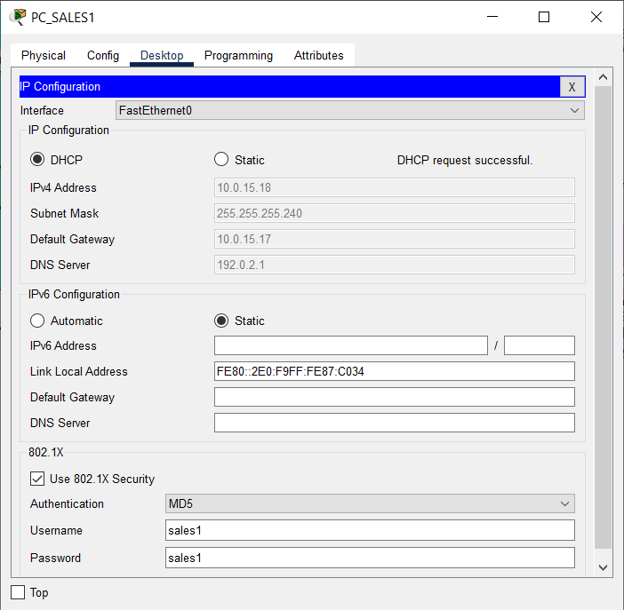
- Configure each PC in VLAN 2 SALES Sumbawa BRANCH as a DHCP client and enable 802.1x security features with authentication accounts, as shown in the table below:
| PC | User | Key |
|---|---|---|
| PC_Sales1 | sales1 | sales1 |
| PC_Sales2 | sales2 | sales2 |
- Verify that each PC on each VLAN has received a dynamic IP address from the DHCP Server.

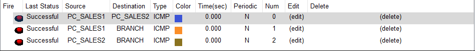
- Using Simple PDU, verify the connection between PC SALES1 and PC SALES2 as well as the BRANCH SUMBAWA router.
Check that the connection is working properly.
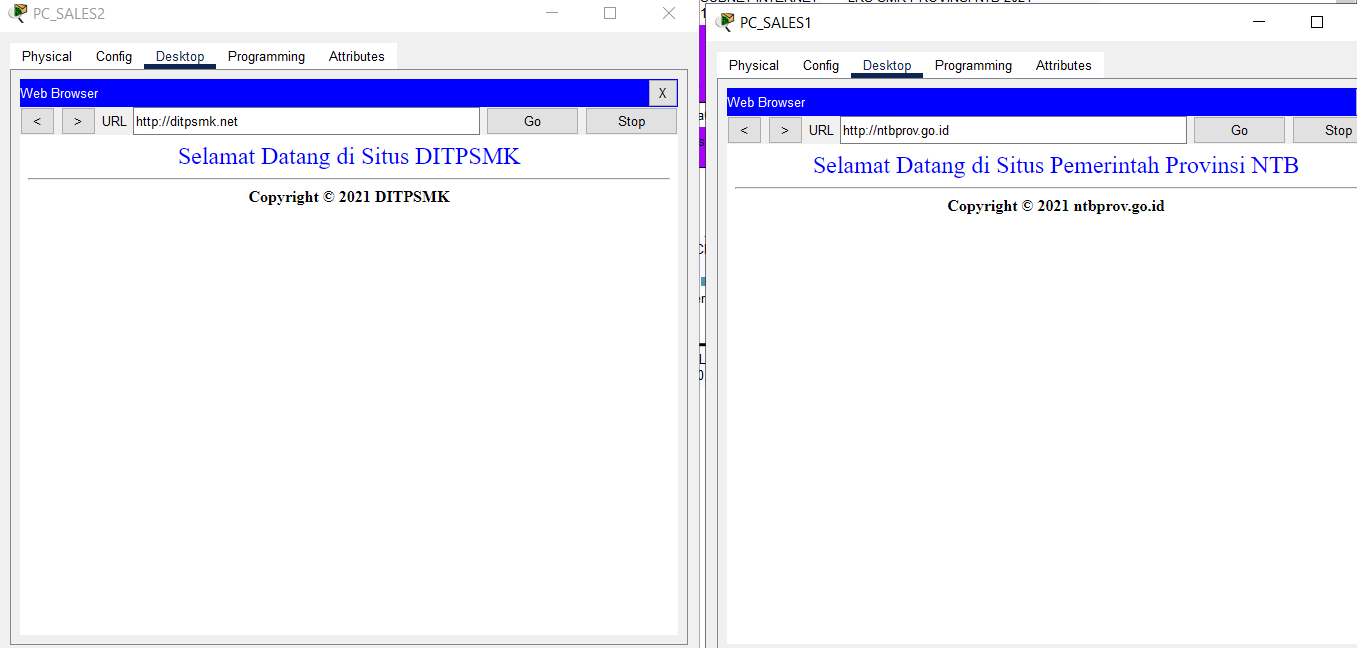
- Use a browser to test the Internet connection of each PC in VLAN 2 SALES by visiting ntbprov.go.id, ditpsmk.net, gmail.com, and universitasbumigora.ac.id.
Check that the connection is working properly.

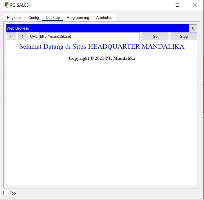
- After completing the NAT configuration on the HQ MATARAM router, access to the HQ Server can be verified by visiting “mandalika.id”
Check that the connection is working properly.
Completed Points: 0%
Task 13: WRT_BRANCH Wireless Router Configuration at BRANCH SUMBAWA
-
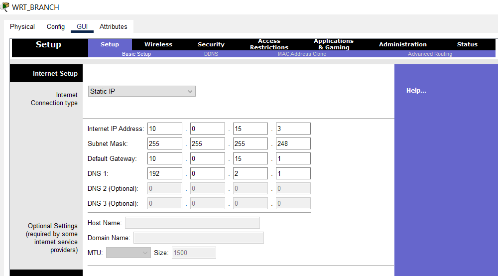
In Internet Setup, configure the IP addressing statically or manually using the following conditions:
- Use the third IP address from subnet 10.0.15.0/29.
- The default gateway uses the first IP address of subnet 10.0.15.0/29.
- The DNS server is using 192.0.2.1.
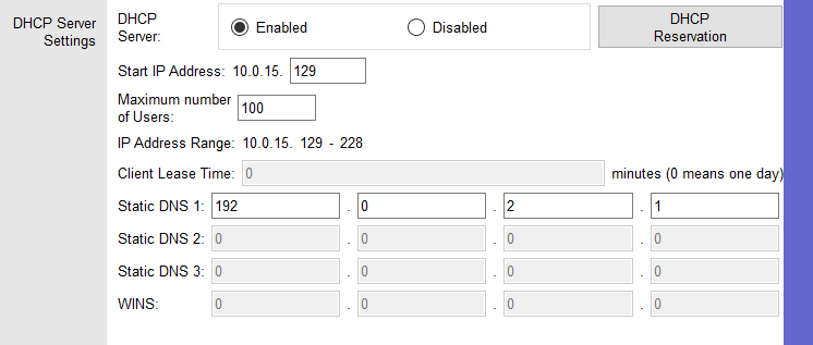
- In Network Setup, configure the IP addressing statically or manually to the first IP address in subnet 10.0.15.128/25.

- Enable the DHCP Server feature and assign dynamically distributed IP addresses to DHCP Clients beginning with the first IP address in subnet 10.0.15.128/25 for a maximum of 100 users.
The DNS Server option is set to 192.0.2.1.
-
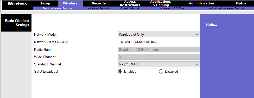
Configure the Wireless feature with the following conditions:
- Network mode “Wireless-G Only”
- Wireless network identifier name or SSID “ENGINEER-MANDALIKA”
- Channel 6
- Enable the SSID Broadcast feature.
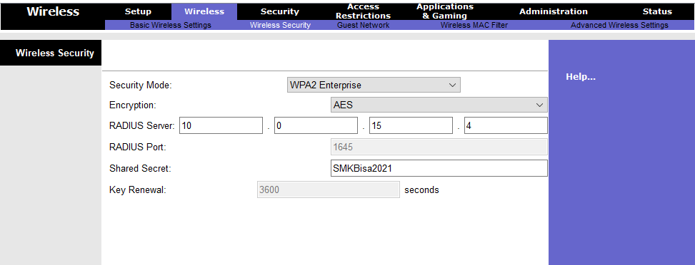
- WPA2 Enterprise security mode with AES encryption
- Radius Server uses the fourth IP address from subnet 10.0.15.0/29 with the shared secret “SMKBisa2021”.
Completed Points: 4%
Task 14: End Device Configuration and Verification at WLAN ENGINEER BRANCH SUMBAWA
-
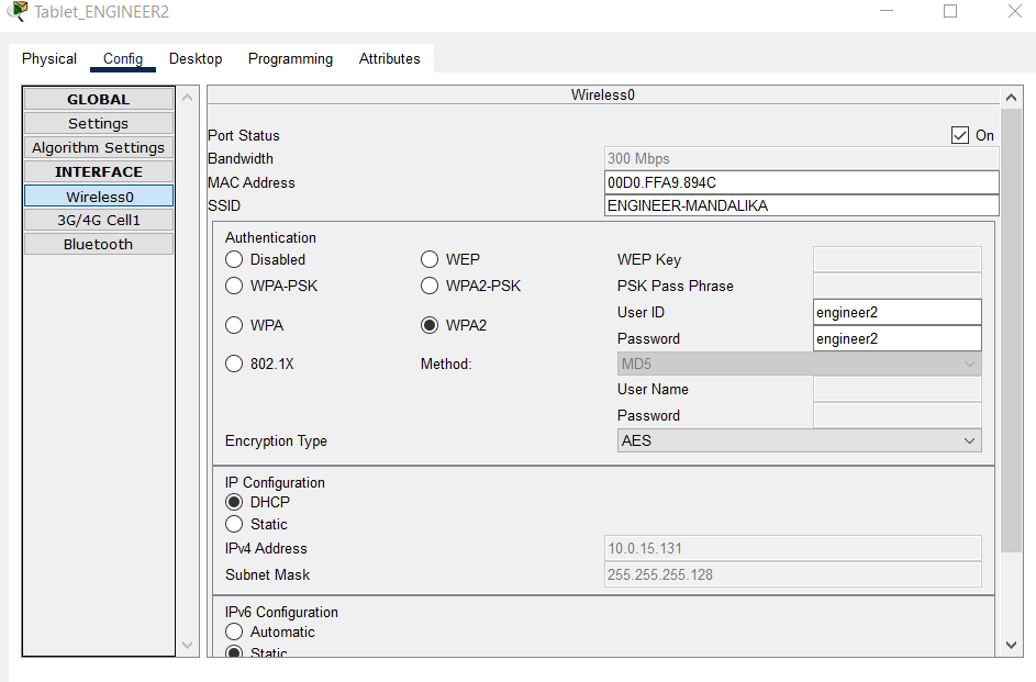
Set the DHCP Client on the Wireless0 interface of each End Device on the WLAN ENGINEER subnet, namely Tablet_ENGINEER1 and Tablet_ENGINEER2, to get dynamic IP addressing from the DHCP Server.
Connect each Tablet on the ENGINEER WLAN subnet to the Wireless Access Point (AP) with the SSID “ENGINEER-MANDALIKA” and the Wireless Security Configuration WPA2-Enterprise.
Use an authentication account as mentioned in the table below:
| Device | Login Name | Password |
|---|---|---|
| Tablet_ENGINEER1 | engineer1 | engineer1 |
| Tablet_ENGINEER2 | engineer2 | engineer2 |
Completed Points: 2%
Task 15: VPN configuration on an HQ MATARAM router using GRE over IPSec and OSPF
-
Create an Extended Named ACL with the name “INTERESTING-TRAFFIC” for:
- Allow GRE traffic from source IP address 192.0.2.18 to destination IP address 192.0.2.26.
- Identify IP traffic from HQ MATARAM Server, 10.0.14.2, to VLAN 2 SALES on BRANCH SUMBAWA router with subnet address 10.0.15.0/29 to the IP address as interesting traffic.
- Identify as interesting traffic IP traffic from VLAN 11 HRD at HQ with subnet address 10.0.11.0/24 to BRANCH Server with address 10.0.15.4.
- Identify as interesting traffic IP traffic from VLAN 12 MARKETING at HQ with subnet address 10.0.12.0/24 to the BRANCH Server with address 10.0.15.4.
HQ(config)#ip access-list extended INTERESTING-TRAFFIC
HQ(config-ext-nacl)#permit gre host 192.0.2.18 host 192.0.2.26
HQ(config-ext-nacl)#permit tcp 10.0.15.0 0.0.0.7 host 10.0.14.2
HQ(config-ext-nacl)#permit tcp 10.0.11.0 0.0.0.255 host 10.0.15.4
HQ(config-ext-nacl)#permit tcp 10.0.12.0 0.0.0.255 host 10.0.15.4
- Configure IKE Phase 1 ISAKMP policy with priority 46 and IKE Phase 2 IPSec policy with sequence 46 on the HQ MATARAM router using the conditions shown in table A & B below:
Table A. Parameter ISAKMP Phase 1 Policy
| Parameter | Router HQ MATARAM |
|---|---|
| Key Distribution Method | ISAKMP |
| Encryption Algorithm | AES 256 |
| Hash Algorithm | SHA-1 |
| Authentication Method | pre-share |
| Key Exchange | DH 5 |
| ISAKMP Key | Mandalika |
HQ(config)#crypto isakmp policy 46
HQ(config-isakmp)#encr aes 256
HQ(config-isakmp)#hash sha
HQ(config-isakmp)#authentication pre-share
HQ(config-isakmp)#group 5
HQ(config)#crypto isakmp key Mandalika address 192.0.2.26
Table B. Parameter ISAKMP Phase 2 Policy
| Parameter | Router HQ MATARAM |
|---|---|
| Transform Set Name | HQ-SET |
| ESP Encryption | esp-aes |
| ESP Authentication | esp-sha-hmac |
| Peer IP Address | 192.0.2.26 |
| Traffic Encrypted | Extended ACL “INTERESTING-TRAFFIC” |
| Crypto Map Name | HQ-MAP |
| SA Establishment | ipsec-isakmp |
HQ(config)#crypto ipsec transform-set HQ-SET esp-aes esp-sha-hmac
HQ(config)#crypto map HQ-MAP 46 ipsec-isakmp
% NOTE: This new crypto map will remain disabled until a peer
and a valid access list have been configured.
HQ(config-crypto-map)#set peer 192.0.2.26
HQ(config-crypto-map)#set transform-set HQ-SET
HQ(config-crypto-map)#match address INTERESTING-TRAFFIC
- Configure the crypto map on the outgoing Serial0/0/0 interface.
HQ(config)#int s0/0/0
HQ(config-if)#crypto map HQ-MAP
*Jan  3 07:16:26.785: %CRYPTO-6-ISAKMP_ON_OFF: ISAKMP is ON
-
Configure a GRE Tunnel over IPSec with the following parameters:
- Use the first IP address of the subnet 10.0.14.4/30 to set the IP address of the tunnel interface 46.
- Configure interface Serial0/0/0 as the source and IP address 192.0.2.26 as the destination for tunnel interface 46’s endpoint.
HQ(config)#int tunnel 46
%LINK-5-CHANGED: Interface Tunnel46, changed state to up
HQ(config-if)#ip address 10.0.14.5 255.255.255.252
HQ(config-if)#tunnel source serial 0/0/0
HQ(config-if)#tunnel destination 192.0.2.26
HQ(config-if)#tunnel mode gre ip
- Add the subnet addresses 10.0.14.0/30, 10.0.14.5/30, 10.0.11.0/24, and 10.0.12.0/24 as part of the OSPF area 0 network in the OSPF routing protocol process-id 46.
HQ(config)#router ospf 46
HQ(config-router)#default-information originate
HQ(config-router)#log-adjacency-changes
HQ(config-router)#network 10.0.14.0 0.0.0.3 area 0
HQ(config-router)#network 10.0.14.5 0.0.0.3 area 0
HQ(config-router)#network 10.0.11.0 0.0.0.255 area 0
HQ(config-router)#network 10.0.12.0 0.0.0.255 area 0
- Verify the configuration to confirm that it complies with the requirements.
HQ#sh run
Building configuration...

Current configuration : 3814 bytes
!
version 15.1
no service timestamps log datetime msec
no service timestamps debug datetime msec
no service password-encryption
!
hostname HQ
!
enable secret 5 $1$mERr$ix/GaeUGI2eMcE7/bu9c2/
!
ip dhcp excluded-address 10.0.11.1
ip dhcp excluded-address 10.0.12.1
ip dhcp excluded-address 10.0.13.1 10.0.13.4
!
ip dhcp pool HRD
network 10.0.11.0 255.255.255.0
default-router 10.0.11.1
dns-server 192.0.2.1
ip dhcp pool MARKETING
network 10.0.12.0 255.255.255.0
default-router 10.0.12.1
dns-server 192.0.2.1
ip dhcp pool NATIVE
network 10.0.13.0 255.255.255.0
default-router 10.0.13.1
dns-server 192.0.2.1
!
aaa new-model
!
aaa authentication login SERVER-AAA group RADIUS local
aaa authentication login default local
!
no ip cef
no ipv6 cef
!
username ISP password 0 LksNTB
username admin privilege 15 secret 5 $1$mERr$ix/GaeUGI2eMcE7/bu9c2/
!
license udi pid CISCO1941/K9 sn FTX1524O1D2-
license boot module c1900 technology-package securityk9
!
crypto isakmp policy 46
encr aes 256
authentication pre-share
group 5
!
crypto isakmp key Mandalika address 192.0.2.26
!
crypto ipsec transform-set HQ-SET esp-aes esp-sha-hmac
!
crypto map HQ-MAP 46 ipsec-isakmp
set peer 192.0.2.26
set transform-set HQ-SET
match address INTERESTING-TRAFFIC
!
ip ssh version 2
ip domain-name mandalika.id
ip name-server 192.0.2.1
!
spanning-tree mode pvst
!
interface Tunnel46
ip address 10.0.14.5 255.255.255.252
mtu 1476
tunnel source Serial0/0/0
tunnel destination 192.0.2.26
!
interface GigabitEthernet0/0
description ROUTER-ON-STICK
no ip address
duplex auto
speed auto
!
interface GigabitEthernet0/0.11
description VLAN 11 HRD
encapsulation dot1Q 11
ip address 10.0.11.1 255.255.255.0
ip nat inside
!
interface GigabitEthernet0/0.12
description VLAN 12 MARKETING
encapsulation dot1Q 12
ip address 10.0.12.1 255.255.255.0
ip nat inside
!
interface GigabitEthernet0/0.13
description VLAN 13 NATIVE
encapsulation dot1Q 13 native
ip address 10.0.13.1 255.255.255.0
ip nat inside
!
interface GigabitEthernet0/1
description TO HQ SERVER
ip address 10.0.14.1 255.255.255.252
ip nat inside
duplex auto
speed auto
!
interface Serial0/0/0
description TO ISP
ip address 192.0.2.18 255.255.255.248
encapsulation ppp
ppp authentication chap
ip nat outside
crypto map HQ-MAP
!
interface Serial0/0/1
no ip address
clock rate 2000000
shutdown
!
interface Vlan1
no ip address
shutdown
!
router ospf 46
log-adjacency-changes
network 10.0.14.0 0.0.0.3 area 0
network 10.0.14.4 0.0.0.3 area 0
network 10.0.11.0 0.0.0.255 area 0
network 10.0.12.0 0.0.0.255 area 0
default-information originate
!
ip nat inside source list ALLOW-INTERNET interface Serial0/0/0 overload
ip nat inside source static 10.0.14.2 192.0.2.19
ip classless
ip route 0.0.0.0 0.0.0.0 192.0.2.17
!
ip flow-export version 9
!
ip access-list extended ALLOW-INTERNET
permit udp any host 192.0.2.1 eq domain
permit tcp 10.0.11.0 0.0.0.255 host 192.0.2.5 eq smtp
permit tcp 10.0.11.0 0.0.0.255 host 192.0.2.5 eq pop3
ip access-list extended INTERESTING-TRAFFIC
permit tcp 10.0.12.0 0.0.0.255 any
permit tcp 10.0.13.0 0.0.0.255 any
permit gre host 192.0.2.18 host 192.0.2.26
permit ip 10.0.15.0 0.0.0.7 host 10.0.14.2
permit ip 10.0.11.0 0.0.0.255 host 10.0.15.4
permit ip 10.0.12.0 0.0.0.255 host 10.0.15.4
!
no cdp run
!
RADIUS server SERVER-AAA
address ipv4 10.0.14.2 auth-port 1645
key NTBJawara2021
RADIUS server 10.0.14.2
address ipv4 10.0.14.2 auth-port 1645
key NTBJawara2021
!
line con 0
login authentication SERVER-AAA
!
line aux 0
!
line vty 0 4
session-limit 5
login authentication SERVER-AAA
transport input ssh
!
ntp authentication-key 46 md5 080F786C211C071606595C567B 7
ntp trusted-key 46
ntp server 192.0.2.2 key 46
!
end

HQ#
Completed Points: 8%
Task 16: VPN configuration on a BRANCH SUMBAWA router using GRE over IPSec and OSPF
-
Create an Extended Named ACL with the name “INTERESTING-TRAFFIC” for:
- Allow GRE traffic from source IP address 192.0.2.26 to destination IP address 192.0.2.18.
- Identify as interesting traffic IP traffic from VLAN 2 SALES on the BRANCH SUMBAWA router with subnet address 10.0.15.0/29 to the IP address of the HQ MATARAM Server, which is 10.0.14.2.
- Identify as interesting traffic IP traffic from the BRANCH Server with address 10.0.15.4 to VLAN 11 HRD with subnet address 10.0.11.0/24 at HQ MATARAM.
- Identify as interesting traffic IP traffic from the BRANCH Server with address 10.0.15.4 to VLAN 12 MARKETING with subnet address 10.0.12.0/24 at HQ MATARAM.
BRANCH(config)#ip access-list extended INTERESTING-TRAFFIC
BRANCH(config-ext-nacl)#permit gre host 192.0.2.26 host 192.0.2.18
BRANCH(config-ext-nacl)#permit ip 10.0.15.0 0.0.0.7 host 10.0.14.2
BRANCH(config-ext-nacl)#permit ip 10.0.11.0 0.0.0.255 host 10.0.15.4
BRANCH(config-ext-nacl)#permit ip 10.0.12.0 0.0.0.255 host 10.0.15.4
- Configure IKE Phase 1 ISAKMP policy with priority 46 and IKE Phase 2 IPSec policy with sequence 46 on the BRANCH SUMBAWA router using the conditions shown in table A & B below:
Table A. Parameter ISAKMP Phase 1 Policy
| Parameter | ROUTER BRANCH SUMBAWA |
|---|---|
| Key Distribution Method | ISAKMP |
| Encryption Algorithm | AES256 |
| Hash Algorithm | SHA-1 |
| Authentication Method | pre-share |
| Key Exchange | DH 5 |
| ISAKMP Key | Mandalika |
BRANCH(config)#crypto isakmp policy 46
BRANCH(config-isakmp)#encr aes 256
BRANCH(config-isakmp)#hash sha
BRANCH(config-isakmp)#authentication pre-share
BRANCH(config-isakmp)#group 5
BRANCH(config)#crypto isakmp key Mandalika address 192.0.2.18
Table B. Parameter ISAKMP Phase 2 Policy
| Parameter | ROUTER BRANCH SUMBAWA |
|---|---|
| Transform Set Name | BRANCH-SET |
| ESP Encryption | esp-aes |
| ESP Authentication | SHA-1 |
| Peer IP Address | 192.0.2.18 |
| Traffic Encrypted | Extended ACL “INTERESTING-TRAFFIC” |
| Crypto Map Name | BRANCH-MAP |
| SA Establishment | ipsec-isakmp |
BRANCH(config)#crypto ipsec transform-set BRANCH-SET esp-aes esp-sha-hmac
BRANCH(config)#crypto map BRANCH-MAP 46 ipsec-isakmp
% NOTE: This new crypto map will remain disabled until a peer
and a valid access list have been configured.
BRANCH(config-crypto-map)#set peer 192.0.2.18
BRANCH(config-crypto-map)#set transform-set BRANCH-SET
BRANCH(config-crypto-map)#match address INTERESTING-TRAFFIC
- Configure the crypto map on the outgoing Serial0/0/1 interface.
BRANCH(config)#int s0/0/1
BRANCH(config-if)#crypto map BRANCH-MAP
*Jan  3 07:16:26.785: %CRYPTO-6-ISAKMP_ON_OFF: ISAKMP is ON
-
Configure a GRE Tunnel over IPSec with the following parameters:
- Use the second IP address of the subnet 10.0.14.4/30 to set the IP address of the tunnel interface 46.
- Configure interface Serial0/0/1 as the source and IP address 192.0.2.26 as the destination for tunnel interface 46’s endpoint.
BRANCH(config)#int tunnel 46
%LINK-5-CHANGED: Interface Tunnel46, changed state to up
BRANCH(config-if)#ip address 10.0.14.6 255.255.255.252
BRANCH(config-if)#tunnel source serial 0/0/1
BRANCH(config-if)#tunnel destination 192.0.2.18
BRANCH(config-if)#tunnel mode gre ip
- Add the subnet addresses 10.0.14.0/30, 10.0.15.0/29 and 10.0.15.16/28 as part of the OSPF area 0 network in the OSPF routing protocol process-id 46.
BRANCH(config)#router ospf 46
BRANCH(config-router)#default-information originate
BRANCH(config-router)#log-adjacency-changes
BRANCH(config-router)#network 10.0.14.4 0.0.0.3 area 0
BRANCH(config-router)#network 10.0.15.0 0.0.0.7 area 0
BRANCH(config-router)#network 10.0.15.16 0.0.0.15 area 0
- Verify the configuration to confirm that it complies with the requirements.
BRANCH#sh run
Building configuration...

Current configuration : 3133 bytes
!
version 15.1
no service timestamps log datetime msec
no service timestamps debug datetime msec
no service password-encryption
!
hostname BRANCH
!
enable secret 5 $1$mERr$ix/GaeUGI2eMcE7/bu9c2/
!
ip dhcp excluded-address 10.0.15.17
!
ip dhcp pool SALES
network 10.0.15.16 255.255.255.240
default-router 10.0.15.17
dns-server 192.0.2.1
!
aaa new-model
!
aaa authentication login SERVER-AAA group RADIUS local
aaa authentication login default local
!
no ip cef
no ipv6 cef
!
username ISP password 0 LksNTB
username admin privilege 15 secret 5 $1$mERr$MmdodDsCCQflw.d5M6q3C.
!
license udi pid CISCO1941/K9 sn FTX15243J7P-
license boot module c1900 technology-package securityk9
!
crypto isakmp policy 46
encr aes 256
authentication pre-share
group 5
!
crypto isakmp key Mandalika address 192.0.2.18
!
crypto ipsec transform-set BRANCH-SET esp-aes esp-sha-hmac
!
crypto map BRANCH-MAP 46 ipsec-isakmp
set peer 192.0.2.18
set transform-set BRANCH-SET
match address INTERESTING-TRAFFIC
!
ip ssh version 2
ip domain-name branch.mandalika.id
ip name-server 192.0.2.1
!
spanning-tree mode pvst
!
interface Tunnel46
ip address 10.0.14.6 255.255.255.252
mtu 1476
tunnel source Serial0/0/1
tunnel destination 192.0.2.18
!
interface GigabitEthernet0/0
description ROUTER-ON-STICK
no ip address
ip nat inside
duplex auto
speed auto
!
interface GigabitEthernet0/0.1
encapsulation dot1Q 1 native
ip address 10.0.15.1 255.255.255.248
ip nat inside
!
interface GigabitEthernet0/0.2
description SALES
encapsulation dot1Q 2
ip address 10.0.15.17 255.255.255.240
ip nat inside
!
interface GigabitEthernet0/1
no ip address
duplex auto
speed auto
shutdown
!
interface Serial0/0/0
no ip address
clock rate 2000000
shutdown
!
interface Serial0/0/1
description TO ISP
ip address 192.0.2.26 255.255.255.248
encapsulation ppp
ppp authentication chap
ip nat outside
crypto map BRANCH-MAP
!
interface Vlan1
no ip address
shutdown
!
router ospf 46
log-adjacency-changes
network 10.0.14.4 0.0.0.3 area 0
network 10.0.15.0 0.0.0.7 area 0
network 10.0.15.16 0.0.0.15 area 0
default-information originate
!
ip nat inside source list ALLOW-INTERNET interface Serial0/0/1 overload
ip nat inside source static 10.0.15.4 192.0.2.27
ip classless
ip route 0.0.0.0 0.0.0.0 192.0.2.25
!
ip flow-export version 9
!
ip access-list standard ALLOW-INTERNET
permit 10.0.15.0 0.0.0.7
permit 10.0.15.16 0.0.0.15
ip access-list extended INTERESTING-TRAFFIC
permit gre host 192.0.2.26 host 192.0.2.18
permit ip 10.0.15.0 0.0.0.7 host 10.0.14.2
permit ip 10.0.11.0 0.0.0.255 host 10.0.15.4
permit ip 10.0.12.0 0.0.0.255 host 10.0.15.4
!
RADIUS server SERVER-AAA
address ipv4 10.0.15.4 auth-port 1645
key NTBJawara2021
RADIUS server 10.0.15.4
address ipv4 10.0.15.4 auth-port 1645
key NTBJawara2021
!
login authentication SERVER-AAA
line con 0
!
line aux 0
!
line vty 0 4
session-limit 5
login authentication SERVER-AAA
transport input ssh
!
ntp authentication-key 46 md5 080F786C211C071606595C567B 7
ntp trusted-key 46
ntp server 192.0.2.2 key 46
!
end

BRANCH#
Completed Points: 8%
Task 17: Verification of VPN Connection from End Device at HQ MATARAM
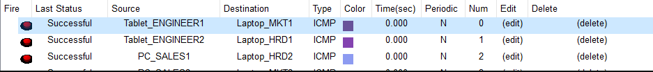
- Use Simple PDU to verify the connection between the End Device on VLAN SALES and WLAN ENGINEER at BRANCH SUMBAWA and the End Device on VLAN HRD and MARKETING at HQ MATARAM.
Check that the connection is working properly.
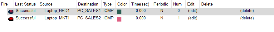
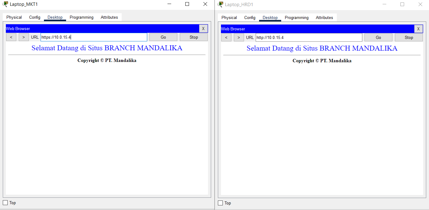
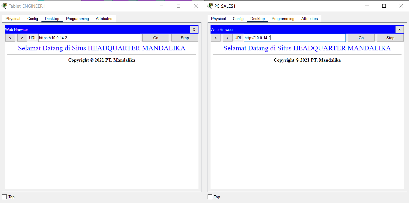
- Use a browser to verify access to HTTP and HTTPS services on the HQ MATARAM Server by entering the addresses http://10.0.14.2 and https://10.0.14.2 from the End Device on VLAN SALES and WLAN ENGINEER from BRANCH SUMBAWA.
Check that HTTP and HTTPS services can be accessed.
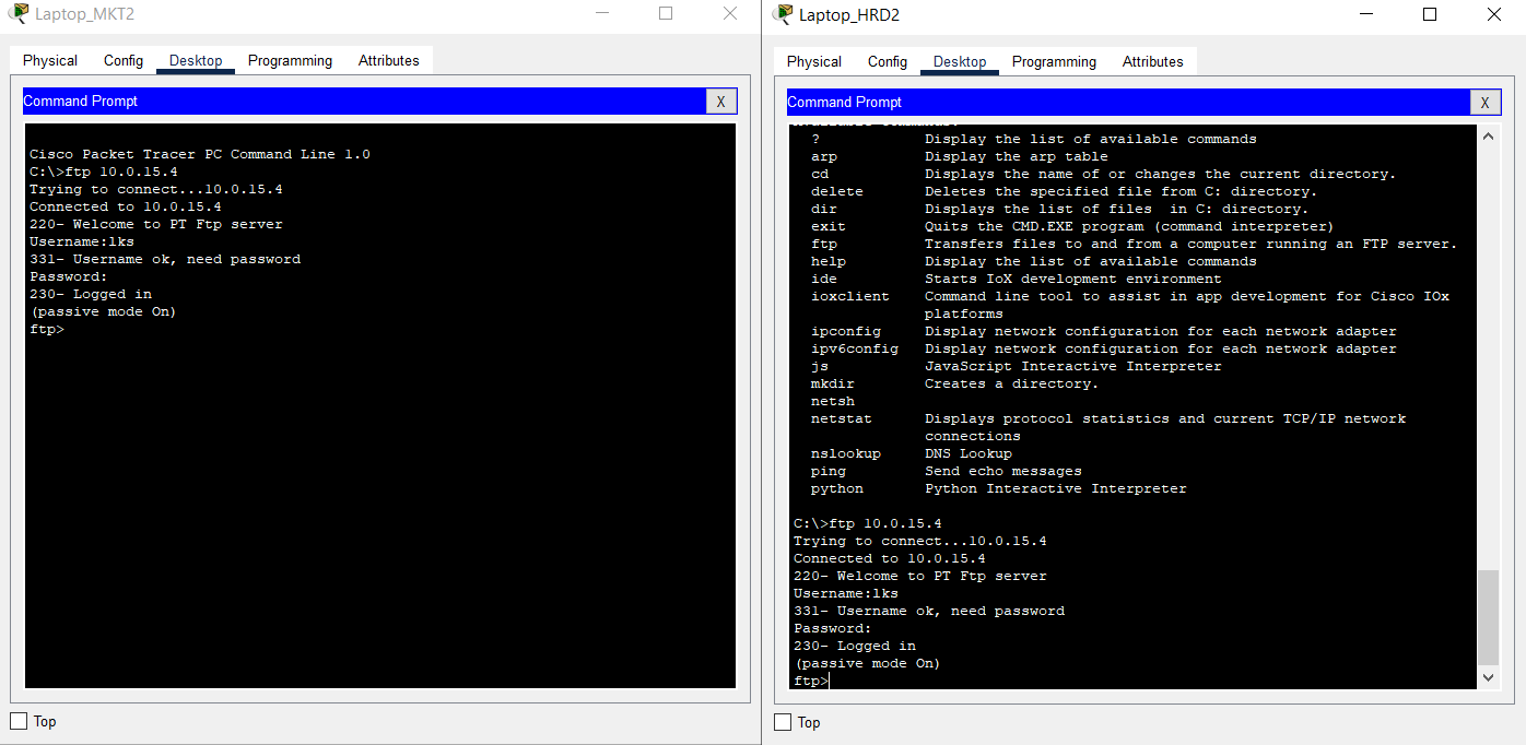
- Access the FTP service on the BRANCH Server using the FTP Client by entering the address 10.0.15.4 from the End Device on the HRD and MARKETING VLAN of HQ MATARAM.
For FTP authentication, the user is “lks” and the password is “ntb."
Check that the FTP service can be accessed.
Completed Points: 0%
Task 18: Verification of VPN Connection from End Device at BRANCH SUMBAWA
- Verification the connection using Simple PDU from the End Device located on VLAN SALES and WLAN ENGINEER from BRANCH SUMBAWA to the End Device located on VLAN HRD and MARKETING at HQ MATARAM.
Make sure the connection is successful.
- Verification of access to HTTP and HTTPS services located at SERVER HQ MATARAM using a browser by accessing the addresses http://10.0.14.2 and https://10.0.14.2 from the End Device located on VLAN SALES and WLAN ENGINEER from BRANCH SUMBAWA.
Make sure HTTP and HTTPS services can be accessed.
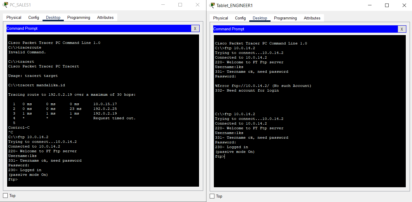
- Access the FTP service on the HQ Server using the FTP Client by entering the address 10.0.14.2 from the End Device on the SALES VLAN and WLAN ENGINEER of BRANCH SUMBAWA.
The user for FTP authentication is “lks” with password “ntb”.
Make sure the FTP service can be accessed.
Completed Points: 0%
Task 19: RBAC Configuration at router HQ MATARAM
- Create a view called “support” and set its password to “mandalika”.
HQ(config)#parser view support
HQ(config-view)#%PARSER-6-VIEW_CREATED: view 'support' successfully created.
HQ(config-view)#secret 5 mandalika
- Configure the view to only run the “ping” and “traceroute” commands, as well as any commands that begin with “show”.
HQ(config-view)#commands exec include ping
HQ(config-view)#commands exec include traceroute
HQ(config-view)#commands exec include all show
- Verify the configuration that has been done to ensure that it is following the requirements.
parser view support
secret 5 $1$mERr$CuHT/qBH1YqIQvmMYg1Ev/
commands exec include ping
commands exec include all show
commands exec include traceroute
Completed Points: 1%
Task 20: RBAC Configuration at router BRANCH SUMBAWA
- Create a view called “helpdesk” and set its password to “mandalika”.
BRANCH(config)#parser view helpdesk
BRANCH(config-view)#%PARSER-6-VIEW_CREATED: view 'helpdesk' successfully created.
BRANCH(config-view)#secret 0 mandalika
- Configure a view that can only run the “show ip protocols,” “display ip route,” “show ip interface short,” “ping,” and “traceroute” commands.
BRANCH(config-view)#commands exec include show ip protocols
BRANCH(config-view)#commands exec include show ip route
BRANCH(config-view)#commands exec include show ip interface brief
BRANCH(config-view)#commands exec include ping
BRANCH(config-view)#commands exec include traceroute
- Verify the configuration that has been carried out to ensure that it is following the requirements.
parser view helpdesk
secret 5 $1$mERr$CuHT/qBH1YqIQvmMYg1Ev/
commands exec include show
commands exec include show ip
commands exec include show ip interface
commands exec include show ip interface brief
commands exec include show ip protocols
commands exec include show ip route
commands exec include traceroute
Completed Points: 1%
Complete Configuration

Router HQ MATARAM
HQ#show run
Building configuration...

Current configuration : 3971 bytes
!
version 15.1
no service timestamps log datetime msec
no service timestamps debug datetime msec
no service password-encryption
!
hostname HQ
!
enable secret 5 $1$mERr$ix/GaeUGI2eMcE7/bu9c2/
!
ip dhcp excluded-address 10.0.11.1
ip dhcp excluded-address 10.0.12.1
ip dhcp excluded-address 10.0.13.1 10.0.13.4
!
ip dhcp pool HRD
network 10.0.11.0 255.255.255.0
default-router 10.0.11.1
dns-server 192.0.2.1
ip dhcp pool MARKETING
network 10.0.12.0 255.255.255.0
default-router 10.0.12.1
dns-server 192.0.2.1
ip dhcp pool NATIVE
network 10.0.13.0 255.255.255.0
default-router 10.0.13.1
dns-server 192.0.2.1
!
aaa new-model
!
aaa authentication login SERVER-AAA group RADIUS local
aaa authentication login default local
!
no ip cef
no ipv6 cef
!
username ISP password 0 LksNTB
username admin privilege 15 secret 5 $1$mERr$ix/GaeUGI2eMcE7/bu9c2/
!
license udi pid CISCO1941/K9 sn FTX1524O1D2-
license boot module c1900 technology-package securityk9
!
crypto isakmp policy 46
encr aes 256
authentication pre-share
group 5
!
crypto isakmp key Mandalika address 192.0.2.26
!
crypto ipsec transform-set HQ-SET esp-aes esp-sha-hmac
!
crypto map HQ-MAP 46 ipsec-isakmp
set peer 192.0.2.26
set transform-set HQ-SET
match address INTERESTING-TRAFFIC
!
ip ssh version 2
ip domain-name mandalika.id
ip name-server 192.0.2.1
!
spanning-tree mode pvst
!
interface Tunnel46
ip address 10.0.14.5 255.255.255.252
mtu 1476
tunnel source Serial0/0/0
tunnel destination 192.0.2.26
!
interface GigabitEthernet0/0
description ROUTER-ON-STICK
no ip address
duplex auto
speed auto
!
interface GigabitEthernet0/0.11
description VLAN 11 HRD
encapsulation dot1Q 11
ip address 10.0.11.1 255.255.255.0
ip nat inside
!
interface GigabitEthernet0/0.12
description VLAN 12 MARKETING
encapsulation dot1Q 12
ip address 10.0.12.1 255.255.255.0
ip nat inside
!
interface GigabitEthernet0/0.13
description VLAN 13 NATIVE
encapsulation dot1Q 13 native
ip address 10.0.13.1 255.255.255.0
ip nat inside
!
interface GigabitEthernet0/1
description TO HQ SERVER
ip address 10.0.14.1 255.255.255.252
ip nat inside
duplex auto
speed auto
!
interface Serial0/0/0
description TO ISP
ip address 192.0.2.18 255.255.255.248
encapsulation ppp
ppp authentication chap
ip nat outside
crypto map HQ-MAP
!
interface Serial0/0/1
no ip address
clock rate 2000000
shutdown
!
interface Vlan1
no ip address
shutdown
!
router ospf 46
log-adjacency-changes
network 10.0.14.0 0.0.0.3 area 0
network 10.0.14.4 0.0.0.3 area 0
network 10.0.11.0 0.0.0.255 area 0
network 10.0.12.0 0.0.0.255 area 0
default-information originate
!
ip nat inside source list ALLOW-INTERNET interface Serial0/0/0 overload
ip nat inside source static 10.0.14.2 192.0.2.19
ip classless
ip route 0.0.0.0 0.0.0.0 192.0.2.17
!
ip flow-export version 9
!
ip access-list extended ALLOW-INTERNET
permit udp any host 192.0.2.1 eq domain
permit tcp 10.0.11.0 0.0.0.255 host 192.0.2.5 eq smtp
permit tcp 10.0.11.0 0.0.0.255 host 192.0.2.5 eq pop3
permit tcp 10.0.12.0 0.0.0.255 any
permit tcp 10.0.13.0 0.0.0.255 any
ip access-list extended INTERESTING-TRAFFIC
permit gre host 192.0.2.18 host 192.0.2.26
permit ip 10.0.15.0 0.0.0.7 host 10.0.14.2
permit ip 10.0.11.0 0.0.0.255 host 10.0.15.4
permit ip 10.0.12.0 0.0.0.255 host 10.0.15.4
!
no cdp run
!
RADIUS server SERVER-AAA
address ipv4 10.0.14.2 auth-port 1645
key NTBJawara2021
RADIUS server 10.0.14.2
address ipv4 10.0.14.2 auth-port 1645
key NTBJawara2021
!
line con 0
login authentication SERVER-AAA
!
line aux 0
!
line vty 0 4
session-limit 5
login authentication SERVER-AAA
transport input ssh
!
parser view support
secret 5 $1$mERr$CuHT/qBH1YqIQvmMYg1Ev/
commands exec include ping
commands exec include all show
commands exec include traceroute
!
ntp authentication-key 46 md5 080F786C211C071606595C567B 7
ntp trusted-key 46
ntp server 192.0.2.2 key 46
!
end


HQ#
Router BRANCH SUMBAWA
BRANCH#sh run
Building configuration...

Current configuration : 3484 bytes
!
version 15.1
no service timestamps log datetime msec
no service timestamps debug datetime msec
no service password-encryption
!
hostname BRANCH
!
enable secret 5 $1$mERr$ix/GaeUGI2eMcE7/bu9c2/
!
ip dhcp excluded-address 10.0.15.17
!
ip dhcp pool SALES
network 10.0.15.16 255.255.255.240
default-router 10.0.15.17
dns-server 192.0.2.1
!
aaa new-model
!
aaa authentication login SERVER-AAA group RADIUS local
aaa authentication login default local
!
no ip cef
no ipv6 cef
!
username ISP password 0 LksNTB
username admin privilege 15 secret 5 $1$mERr$MmdodDsCCQflw.d5M6q3C.
!
license udi pid CISCO1941/K9 sn FTX15243J7P-
license boot module c1900 technology-package securityk9
!
crypto isakmp policy 46
encr aes 256
authentication pre-share
group 5
!
crypto isakmp key Mandalika address 192.0.2.18
!
crypto ipsec transform-set BRANCH-SET esp-aes esp-sha-hmac
!
crypto map BRANCH-MAP 46 ipsec-isakmp
set peer 192.0.2.18
set transform-set BRANCH-SET
match address INTERESTING-TRAFFIC
!
ip ssh version 2
ip domain-name branch.mandalika.id
ip name-server 192.0.2.1
!
spanning-tree mode pvst
!
interface Tunnel46
ip address 10.0.14.6 255.255.255.252
mtu 1476
tunnel source Serial0/0/1
tunnel destination 192.0.2.18
!
interface GigabitEthernet0/0
description ROUTER-ON-STICK
no ip address
ip nat inside
duplex auto
speed auto
!
interface GigabitEthernet0/0.1
encapsulation dot1Q 1 native
ip address 10.0.15.1 255.255.255.248
ip nat inside
!
interface GigabitEthernet0/0.2
description SALES
encapsulation dot1Q 2
ip address 10.0.15.17 255.255.255.240
ip nat inside
!
interface GigabitEthernet0/1
no ip address
duplex auto
speed auto
shutdown
!
interface Serial0/0/0
no ip address
clock rate 2000000
shutdown
!
interface Serial0/0/1
description TO ISP
ip address 192.0.2.26 255.255.255.248
encapsulation ppp
ppp authentication chap
ip nat outside
crypto map BRANCH-MAP
!
interface Vlan1
no ip address
shutdown
!
router ospf 46
log-adjacency-changes
network 10.0.14.4 0.0.0.3 area 0
network 10.0.15.0 0.0.0.7 area 0
network 10.0.15.16 0.0.0.15 area 0
default-information originate
!
ip nat inside source list ALLOW-INTERNET interface Serial0/0/1 overload
ip nat inside source static 10.0.15.4 192.0.2.27
ip classless
ip route 0.0.0.0 0.0.0.0 192.0.2.25
!
ip flow-export version 9
!
ip access-list standard ALLOW-INTERNET
permit 10.0.15.0 0.0.0.7
permit 10.0.15.16 0.0.0.15
ip access-list extended INTERESTING-TRAFFIC
permit gre host 192.0.2.26 host 192.0.2.18
permit ip 10.0.15.0 0.0.0.7 host 10.0.14.2
permit ip 10.0.11.0 0.0.0.255 host 10.0.15.4
permit ip 10.0.12.0 0.0.0.255 host 10.0.15.4
!
RADIUS server SERVER-AAA
address ipv4 10.0.15.4 auth-port 1645
key NTBJawara2021
RADIUS server 10.0.15.4
address ipv4 10.0.15.4 auth-port 1645
key NTBJawara2021
!
line con 0
login authentication SERVER-AAA
!
line aux 0
!
line vty 0 4
session-limit 5
login authentication SERVER-AAA
transport input ssh
!
parser view helpdesk
secret 5 $1$mERr$CuHT/qBH1YqIQvmMYg1Ev/
commands exec include ping
commands exec include show
commands exec include show ip
commands exec include show ip interface
commands exec include show ip interface brief
commands exec include show ip protocols
commands exec include show ip route
commands exec include traceroute
!
ntp authentication-key 46 md5 080F786C211C071606595C567B 7
ntp trusted-key 46
ntp server 192.0.2.2 key 46
!
end


BRANCH#
Summary
It was enjoyable for me, specifically the VPN section, because I rarely use it in my daily work.
Unfortunately, I ran into issues where the “WLAN ENGINEER” section could not be pinged from the client at HQ MATARAM, while the “WLAN ENGINEER” could ping towards the HQ MATARAM client.
My guess is in the OSPF section.
Finally, I was unable to complete the task completely, either due to a Packet Tracer problem or an incorrect setting.
Please let me know if you spot any setting problems or typos. Thank you very much.